|
. . . . AND THOSE AROUND TRING
PLATES
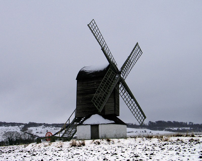
Plate 1: Pitstone Mill, Buckinghamshire.
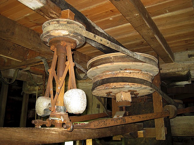
Plate 2: Centrifugal governor, Pitstone Mill,
Buckinghamshire.
|
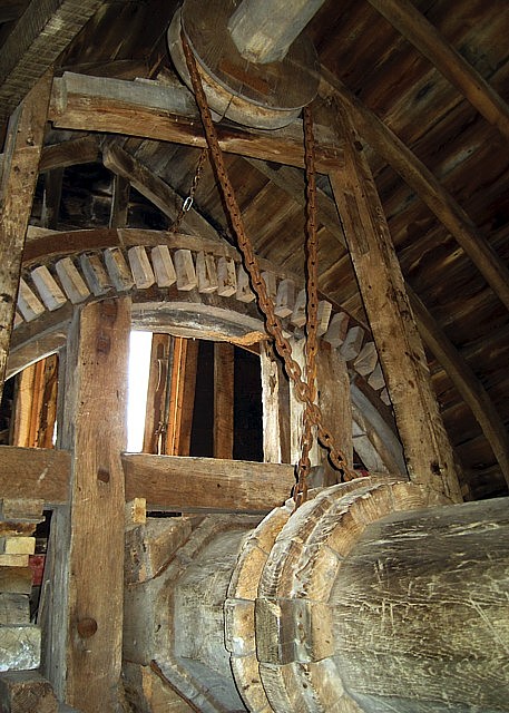
Plate 3: Windshaft and brake wheel, Pitstone Mill. The
chain extending to the pulley at the top of the picture drives the
auxiliary shaft, which powers the sack hoist and other auxiliary
machinery. |
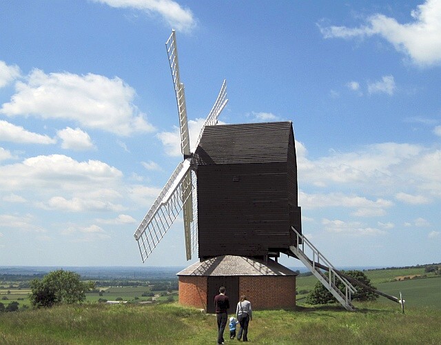
Plate 4: Brill Post Mill, Brill, Buckinghamshire.
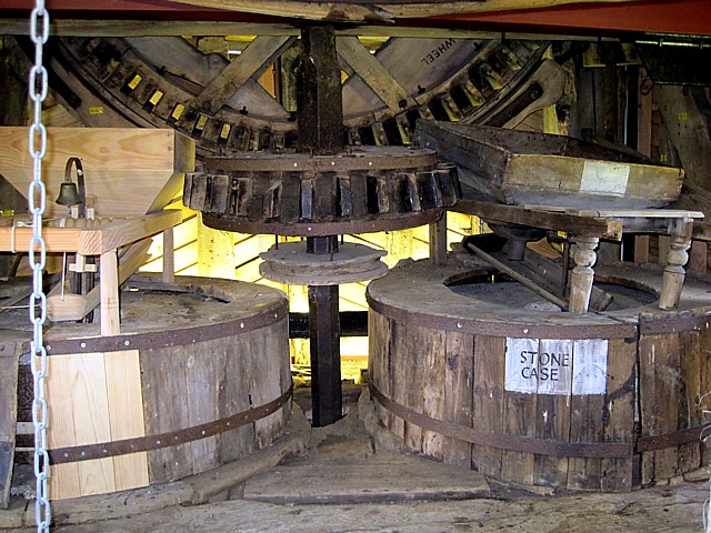
Plate 5: Brake wheel, wallower and (under-driven) millstones,
Brill post mill.
|
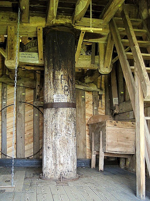
Plate 6: Brill post mill — the main post and resting on it,
the crown tree, which supports the mill’s superstructure (a.k.a. the
‘buck’). The meal bin is to the right of the post and just
visible at its top left is the great spur wheel. |
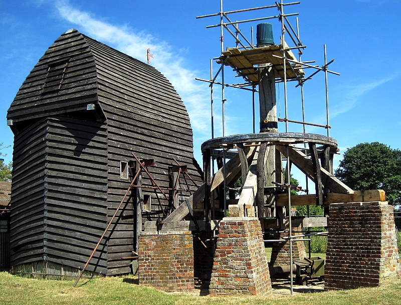
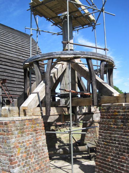
Plate 7: Chinnor post mill in course of reconstruction.
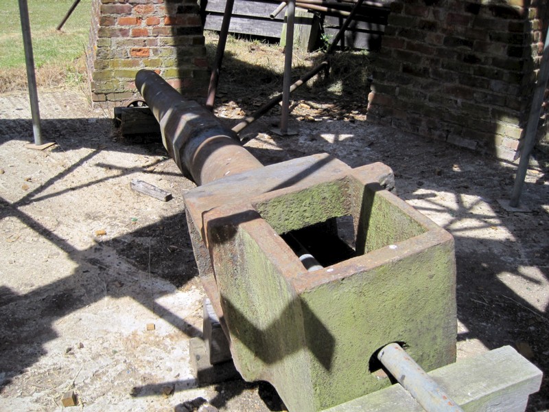
Plate 8: Chinnor post mill — cast-iron windshaft with poll-head
(nearest the camera).
|
Plate 9: Chinnor post mill — main post, quarter bars,
cross-trees and brick piers. This mill is unusual in having
three (rather than two) cross trees and six (rather than four)
‘quarter bars’. The ring stabilises the buck (superstructure). |
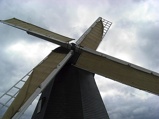
Plate 10: Lacey Green smock mill, Buckinghamshire.
Two of the mill’s sweeps are in full sail, two in three-quarter.
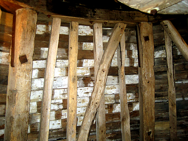
Plate 11: Internal structure of a smock mill. The large
timbers are its ‘cant posts’.
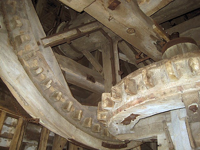
Plate 12: Lacey Green smock mill, Buckinghamshire.
Brake wheel and wallower.
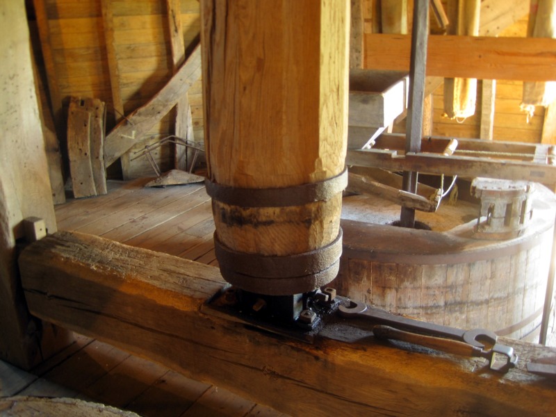
Plate 13: Upright shaft and its bearing, Lacey Green smock
mill.
|
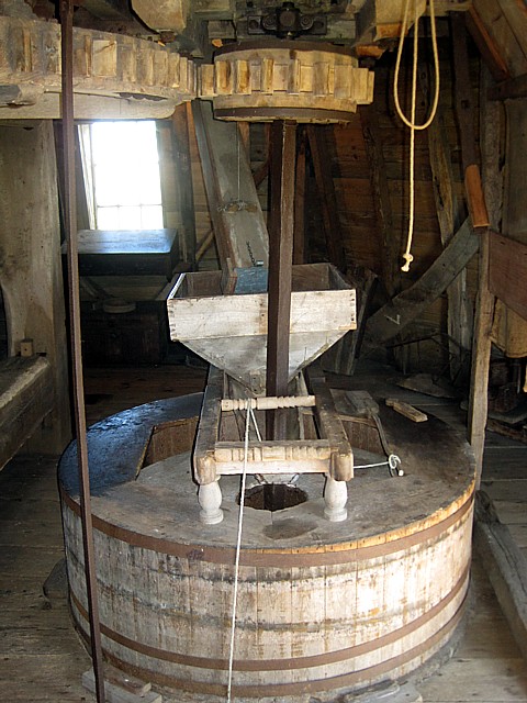
Plate 14: Lacey Green smock mill. Top left, great spur
wheel; top centre, stone nut. Millstones driven from above are
described as being ‘over-driven’. |
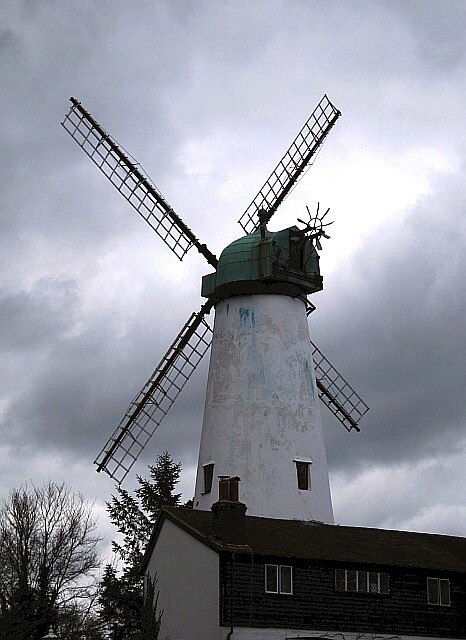
Plate 15: Hawridge tower mill, Buckinghamshire. The
sails are purely decorative.
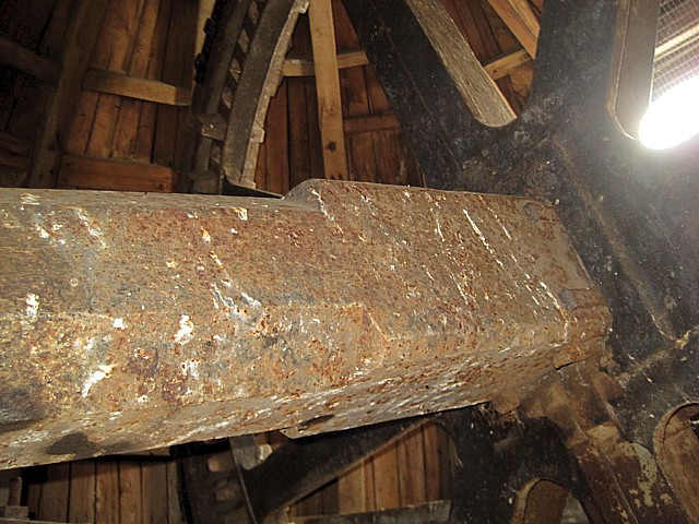
Plate 16: Hawridge tower mill, Buckinghamshire — iron wind
shaft and brake wheel.
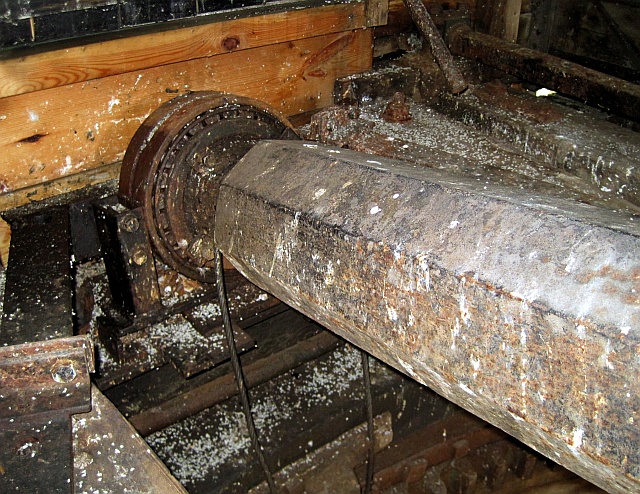
Plate 17: Hawridge tower mill, Buckinghamshire — iron
windshaft and roller bearing.
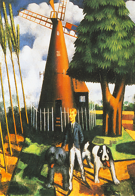
Plate 18: Gilbert Cannon outside Hawridge tower mill.
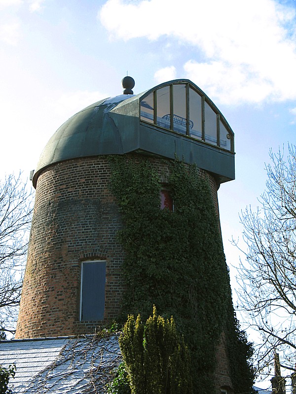
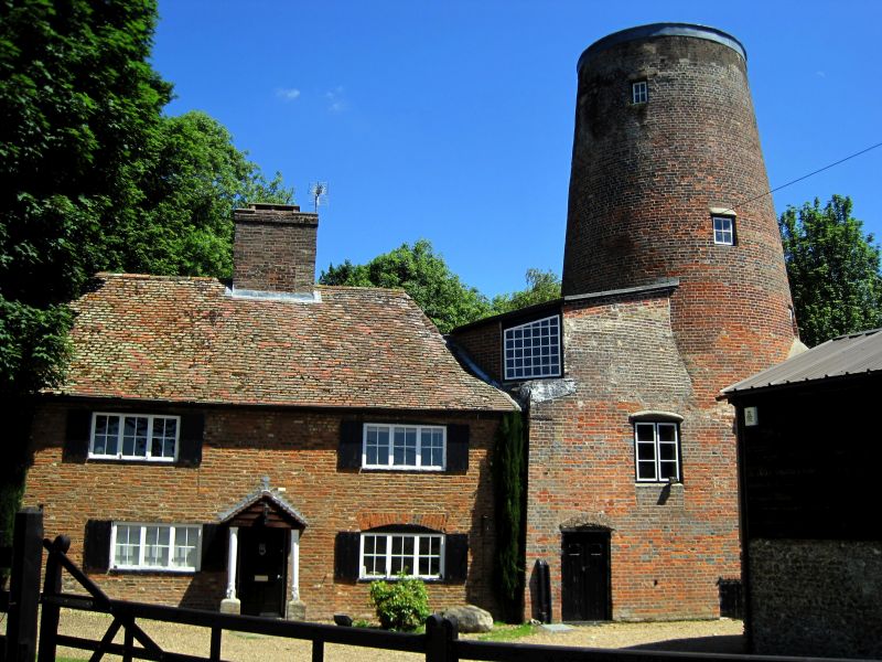
Plate 19: Goldfield tower mill, Tring.

Plate 20: Inside the cap, Goldfield tower mill, Tring.
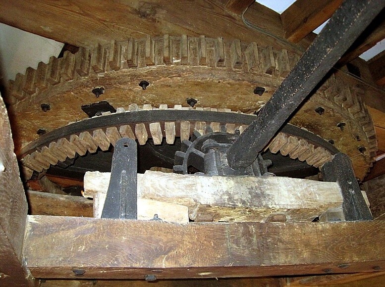
Plate 21: Great spur wheel, Goldfield tower mill, Tring.
The iron to wood coupling seen here ran more
smoothly and was cheaper to maintain than iron to iron. The
shaft was connected to a steam engine.
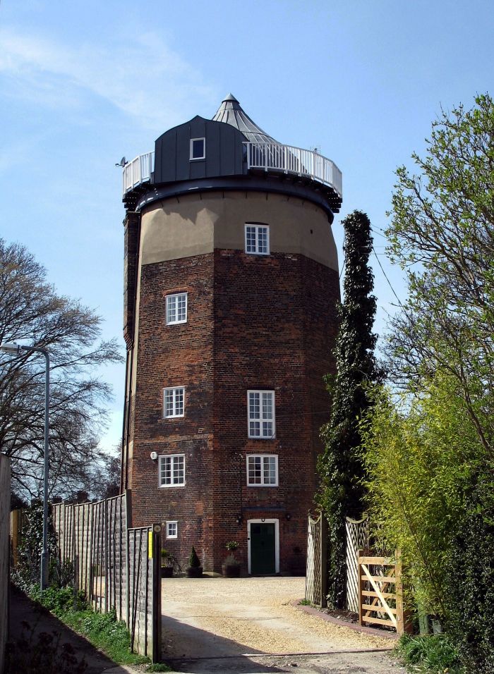
Plate 22: the great octagonal tower mill at Wendover,
Buckinghamshire.
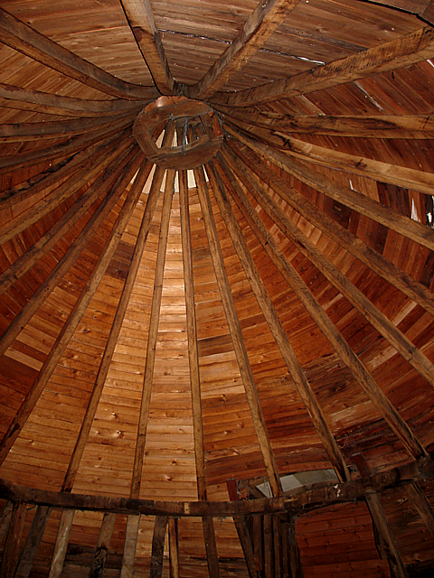
Plate 23: Wendover tower mill, looking up at the apex of the
cap.
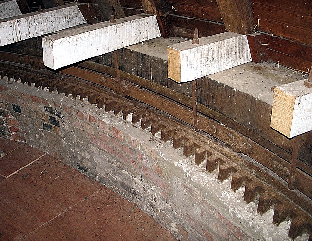
Plate 24: the curb, Wendover tower mill. The rack
contains 300 iron teeth. The cap
rests on 30 evenly-spaced iron rollers, two of them being just
visible above the rack.
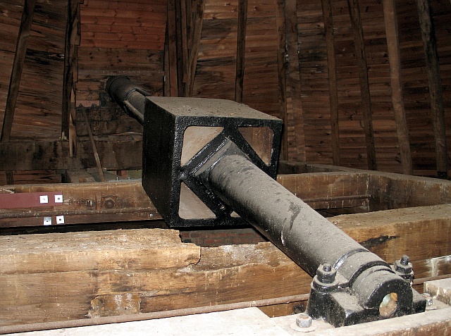
Plate 25: the iron windshaft and its bearing, Wendover tower
mill.
The casting in the centre of the shaft carried the brake wheel.
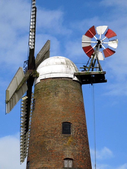
Plate 26: Quainton tower mill, Buckinghamshire.
The twist in the sails improves their performance.
|
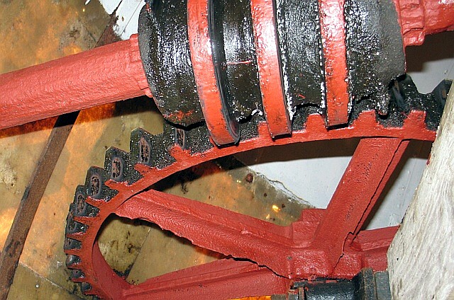
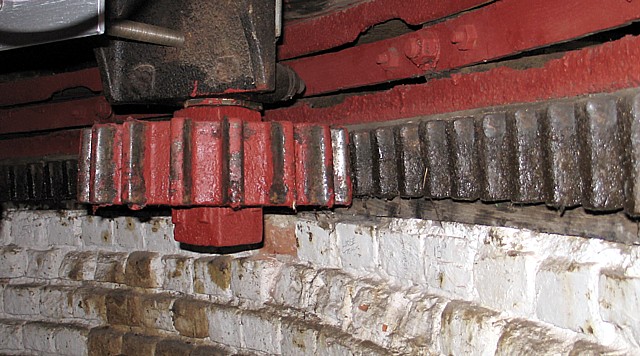
Plates 27 and 28: Quainton tower mill, Buckinghamshire.
The worm gear above, when driven by the fantail, rotates the cog and
its spindle. The spindle terminates on the cog shown below,
which in turn engages with the rack, which extends around the
perimeter of the cap. Through this system of shafts and
gearing, the rotating fantail keeps the cap facing into wind. |
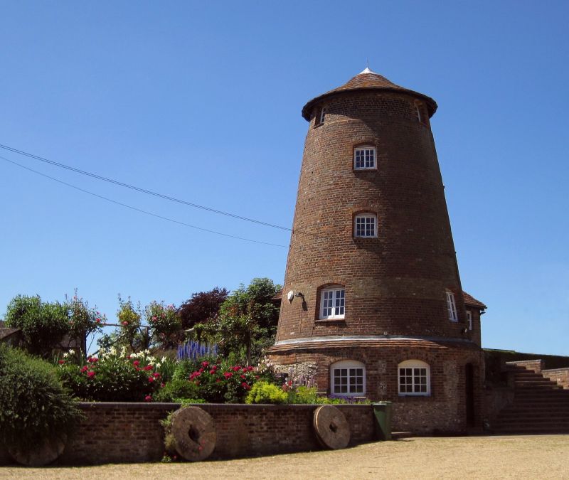
Plates 29 and 30: Edlesborough and Doolittle mills.
.jpg)
Plate 31: Thorpness post mill, Suffolk. An example of a
post mill fitted with a fantail.
|