|
|
NOTES
AND EXTRACTS
ON THE HISTORY OF THE
LONDON & BIRMINGHAM RAILWAY
CHAPTER
10
CONSTRUCTION
―
TRACK AND SIGNALLING
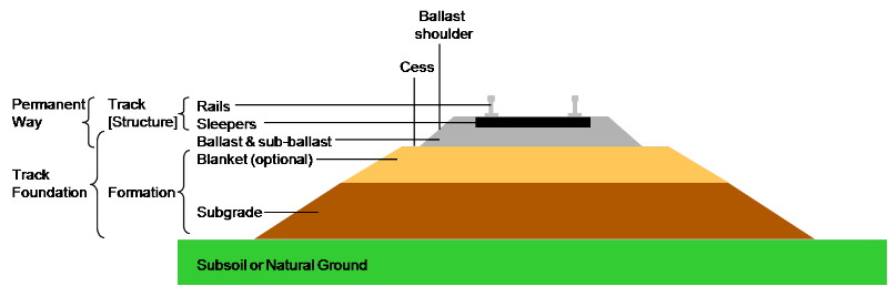
THE PERMANENT WAY
“I would here remark, that when competition
was developing the present high velocities upon railways, generally
Mr. Robert Stephenson gave it in evidence as his opinion, that the
limit would be found, not in any particular gauge, or in the
evaporating power of the engines, but in the economic endurance
of the permanent way to bear the additional weight which must, as a
matter of necessity, accompany every increase of speed. Time
is, in my opinion, rapidly demonstrating the truth of this
observation.”
From a Report by R.B. Dockray,
Engineer to the LNWR, 23rd August 1848.
Picture
Bermicourt
The term
‘permanent way’ originated in the early days of mainline railway
construction. Contractors laid temporary track on which to run the
earth wagons that they used to remove spoil from excavations and
carry it onto embankments being formed. This lightweight track
could easily be slewed into different positions to better
accommodate their operations as they progressed. When the work was
complete, the ‘contractor’s way’ was dismantled and moved
elsewhere. Ballast was then spread over the trackbed to provide
support and drainage, and onto this was laid the railway. The
rails, fasteners, sleepers and ballast that was to carry the railway
company’s traffic became known as the ‘permanent way’, despite
each of these components being anything but permanent, their
lifespan depending on factors such as the type and volume of
traffic, atmospheric conditions, curves and braking conditions.
 Today the
dominant form of track consists of flat-bottom welded steel rails [1]
of uniform cross-section supported on timber or pre-stressed
concrete sleepers laid on crushed stone ballast. This position was
only reached after many years of experiment and development. Today the
dominant form of track consists of flat-bottom welded steel rails [1]
of uniform cross-section supported on timber or pre-stressed
concrete sleepers laid on crushed stone ballast. This position was
only reached after many years of experiment and development.
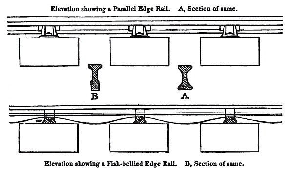
The first breakthrough came in 1820, when John Birkinshaw of
Bedlington Ironworks in Northumberland developed rolled wrought iron
fish-bellied rails in 15 feet lengths. They were strong enough to
bear the stresses imposed by a locomotive hauled train ― which
earlier brittle cast-iron rails, even in shorter lengths, were not
― and they marked the beginning of the modern rail era. Rails of
the Birkinshaw type were used on the Stockton and Darlington and the
Liverpool and Manchester railways:
“The material of which the Rails were to be
composed, whether of cast or forged iron, was a matter of some
importance. Each description of Rail has its advocates; but after
due consideration and enquiry into their respective merits, the
Directors [of the Liverpool and Manchester railway]
determined to adopt the forged or rolled iron Rail, in lengths of
five yards each . . . . A similar Rail is used on the
[Stockton and] Darlington way, but somewhat
lighter; the Darlington Rail weighing 28lb., and the Liverpool and
Manchester 35 lb., per lineal yard. The Rails are supported every
three feet, on stone blocks, each block containing nearly four cubic
feet of stone. Two holes, six inches deep, and an inch diameter,
are drilled in each block, and into these are driven oak plugs, and
the cast-iron chairs or pedestals to which the Rail is immediately
fitted and fastened, are firmly spiked down to the oak plugs,
forming altogether a construction of great solidity and strength.
On the embankments, where the foundation may be expected to subside,
the Rails are laid on oak sleepers.”
Remarks on the Comparative
Merits of Cast Metal and Malleable Iron Railways,
Longridge and Birkinshaw (1832).

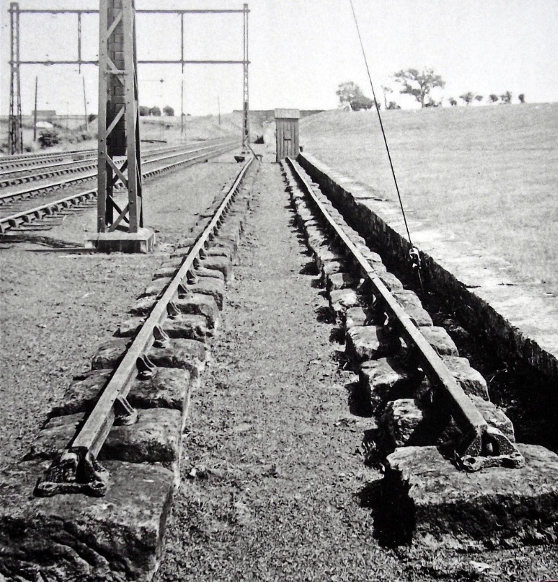
A section of fish-bellied
rail on stone block sleepers, Stockton & Darlington Railway.
Darlington Railway Museum.
Horse-drawn wagonways had used rails mounted on rows of stone
blocks, but without any cross ties between them to maintain the
correct gauge (unnecessary for light, slow-moving traffic). The use
of blocks left a clear path for the horses’ hooves, which would have
been denied them had transverse wooden sleepers been put down,
unless they were buried in the ballast where they would have been
more prone to rot. And so the builders of the first public
locomotive-worked railways, Robert Stephenson among them, followed
the wagonway model. Joseph Locke was a notable exception. [2]
Locke, Engineer to the Grand Junction Railway, [3]
realised that locomotive traction required a degree of flexibility
in the track that stone blocks did not provide, but that transverse
wooden sleepers laid at intervals did. Furthermore, the stresses
imposed on the track by much heavier, faster moving traffic,
required the rails to be held firmly to gauge ― wooden sleepers met
this requirement much more readily than stone blocks, which traffic
gradually eased out of gauge unless the blocks were fitted at
intervals with metal tie rods.
Rails fastened in iron
chairs laid on stone block sleepers.
There were other disadvantages associated with stone block
sleepers. The impact of train wheels against their unyielding
surface caused the rails to shake loose in their supporting chairs;
their lack of elasticity provided a train’s passengers with an
uncomfortable ride ― as one contemporary commentator put it, “The
clatter caused by the stone blocks, which were used before the
wooden sleepers replaced them, added to the unpleasantness of the
journey” ― and, generally speaking, they were more expensive
than wood. However, one problem that did not affect stone was rot,
which was probably an important factor in its choice.
During the construction of the London and Birmingham Railway, the
preparation much in vogue for protecting timber against rot was that
discovered by John Howard Kyan and first patented in 1832:
“Kyan’s Patent Preparation ― a process of
preserving timber from the dry rot, recently invented by Mr. Kyan,
consisting of a solution of corrosive sublimate [mercuric
chloride], in which the timber is immersed,
whereby the primary element of fermentation is neutralized, and the
fibre of the wood rendered indestructible. It also effectually
seasons the timber, occupying a space of only two or three months
instead of from two to six years, which is usually consumed in
laying it to dry, by the common method; and it also protects it from
the ravages of insects. The preparation has become generally
employed for railway sleepers, and for all timbering employed in
engineering works, which from their exposure to the weather are very
liable to premature decay.”
A Glossary of Civil Engineering,
S. C. Brees (1844).
The claims made in favour of ‘kyanizing’ were such that many
railways built at the time applied it to their sleepers. However,
the solution was highly poisonous, the process was expensive and, if
not applied properly, its efficacy was limited or neutralised.
Nevertheless, kyanizing was considered the best rot preventive then
available and, despite its drawbacks, it was used on those sections
of the London and Birmingham Railway laid with wooden sleepers.
These were mainly embankments and other sections where the formation
was more likely to settle when under load:
“On embankments transverse sleepers of
Scotch fir, larch, and oak, are used as the foundation for the
rails; and in cuttings, stone blocks; but on many parts of the line
sleepers have been substituted to a great extent. The are 7 feet in
length, having a scantling of 9 inches by 5 inches; the cost is
about 7s. each, exclusive of kyanizing, which adds 9d. additional to
each sleeper.”
The London and Birmingham permanent
way,
from The Railways of Great Britain and Ireland, Wishaw
(1842).
However, the results obtained from the process were mixed. On the
Great Western Railway it was found to be satisfactory, but on the
London and Birmingham it was not, and was soon discarded:
“With reference to the durability produced
by this process, accounts are somewhat contradictory. How far
success in this respect may be owing to careful and complete
performance, or, on the other hand, failure be promoted by careless
and incomplete Kyanizing, we have no means of determining. Upon the
application of the process for the Great Western Railway, it was
reported in August, 1843, that a part taken from the centre of one
of the longitudinal timbers forming the base of the railway which
had been Kyanized six years before, was as sound as on the day on
which it was first put down . . . . On the London and Birmingham
Railway, on the contrary, the engineer reported, that the sleepers,
which were all Kyanized, were, after lying three years, found to
exhibit symptoms of decay, ― that many of them had been
removed absolutely rotten, and Kyan’s process had been consequently
abandoned.”
Professional Papers of the Corps
of Royal Engineers (1845).
Kyanizing gradually fell out of favour after a patent covering the
use of ‘creosote’ [4] to treat timber was taken
out by John Bethell in 1838. The ‘Bethell process’ involved sealing
timber in a pressure chamber and then applying a vacuum to remove
air and moisture from its cells. The timber was then
pressure-treated in order to impregnate it with the preservative,
following which the vacuum was reapplied to separate the excess
solution from the timber:
“This process has been adopted by the
following eminent engineers, viz. Mr. Robert Stephenson, Mr. Brunel,
Mr. Bidder, Mr. Brathwaite, Mr. Buck, Mr. Harris, Mr. Wickstead, Mr.
Pritchard, and others; and has been used with the greatest success
on the Great Western railway, the Bristol and Exeter railway, the
Manchester and Birmingham railway, the North Eastern, the South
Eastern, the Stockton and Darlington, and at Shoreham Harbor; and
lately, in consequence of the excellent appearance of the
prepared sleepers, after three years exposure to the weather, an
order has been issued by Mr. Robert Stephenson, that the sleepers
hereafter to be used on the London and Birmingham railway are to be
prepared with it before being put down.”
Recent improvements in arts,
manufactures, and mines, Andrew Ure (1845).
Fortuitously, creosote became established as an affective rot
protection agent at much the same time that wooden sleepers were
replacing stone blocks for supporting rails:
“I find, as a general result, that stone
blocks are not adapted to high speeds, ― they are rigid, the chairs
cannot be retained firmly upon them, and from this cause they are
subject to rapid wear; and as they are in this district very
expensive in first cost, I should recommend their being renewed with
sleepers.”
From a Report by R. B. Dockray,
Engineer to the LNWR, 23rd August 1848.
The
Company was then faced with the task of disposing of many thousands
of tons of redundant stone blocks, which, according to Lecount, had
cost the Company dear:
“The stone blocks for the whole line may be
estimated at 152,460 tons, and their cost at £180,000; the expense
being pretty nearly divided into three parts ― viz., one-third for
the cost of stone, one-third for freight to the Thames, and the
remainder for delivery on various parts of the works.”
The London and Birmingham Railway,
Roscoe and Lecount (1839).
|
|
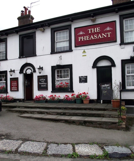
Redundant stone block sleepers in use
as a boundary marker
outside the Pheasant public house at
Tring.
|
 |
|
“The difficulties, which attended the use
of stone blocks at length led to the substitution of wooden
sleepers, which have now almost altogether superseded them. The
traveller on the London and Birmingham line may notice, at
intervals, extensive piles of the blocks which have been removed,
any number of which may be purchased for about eighteen pence each.
Wooden sleepers are now almost universally employed, and they
serve at once as a support for the chair and rails, and as ties for
keeping the line in gauge.”
Our Iron Roads, F. S. Williams
(1852).
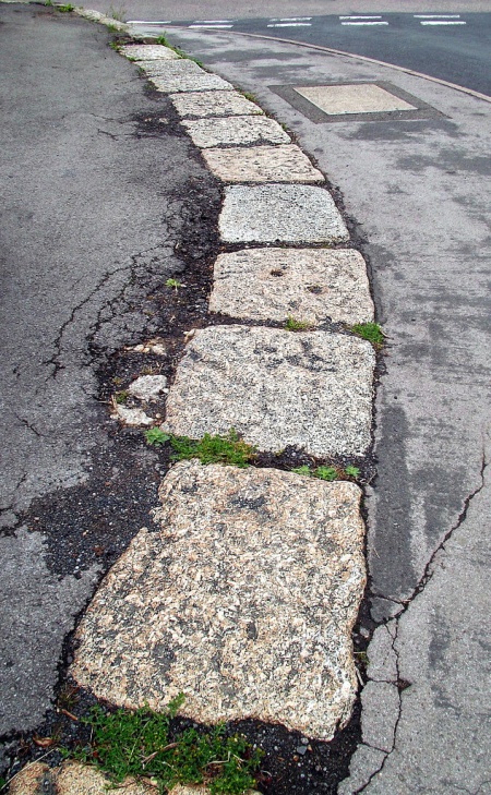
Today, many of the Railway’s former stone sleepers can be seen in
use as coping stones along the banks of the nearby Grand Junction
Canal. Some found their way into more domestic and decorative
applications, such as Abbot’s Hill House (King’s Langley), once home
to the paper magnate John Dickinson, which is built with redundant
blocks, and the attractive granite boundary markers fronting the
Pheasant public house at Tring (above).
The use of stone blocks undoubtedly led to significant wasted
investment, which Locke, then building the Grand Junction Railway,
managed to avoid to a great extent. [5] But
problems with the Railway’s permanent way did not rest solely on the
question of sleepers. The use of fish-bellied rails was another
instance of obsolete technology being employed, [6]
while the correct spacing of the supporting chairs (and hence of the
blocks or sleepers) became yet a further problem:
“The next [General]
meeting was in August 1835. The money then expended was £639,051;
and eighty-six miles of the railway were let to contractors, below
the estimates of the engineer-in-chief, and two-thirds of the whole
land purchased. This was the season of brightness and hope; no
reverses had come on, and all was sunshine and harmony, except
the unfortunate discussions on the rails question.”
The History of the Railway
Connecting London and Birmingham, Peter Lecount (1839).
|
|
Although
Lecount does not state it explicitly, he nevertheless gives the
impression that on the question of rails the exchange of views
between Stephenson, the Board, and their consultants, may have been
frank.

Fish-bellied line showing (in plan)
the half-lapped joint between the rails.
|
 |
|
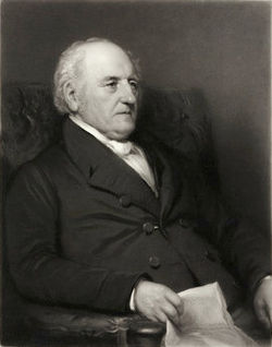
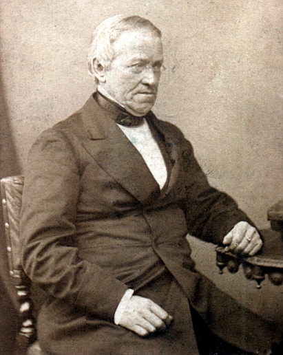
Peter Barlow FRS
(1776-1862),
mathematician and
physicist. |
The
Railway was originally to be laid on the same plan as that adopted
by the Liverpool and Manchester Railway ― wrought iron, fish-bellied
rails of 50 lbs. per yard (Liverpool first used 35 lbs.) laid mostly
on stone blocks, the supporting chairs being set at 3 feet intervals
and the joints between the rails being half-lapped. The chairs were
to be of Stephenson’s patent design.
At an early stage in construction some Board members became
dissatisfied with Stephenson’s plan for the track. The reason for
this is unclear, but as the debate that later took place on sourcing
locomotives for the line centred on objections to Stephenson
receiving royalties for the use of his Patentee class ― and
led to the use of Edward Bury’s engines ― it is possible that the
same objection (among others) applied to the use of his patent rail
chairs:
“The London and Birmingham Railway Company,
after a long discussion, decided to try four and five feet
[chair spacing] with a parallel form
instead of a fish-belly, which, requiring one third more height in
the chair, had in addition to other disadvantages, that of being
more liable to wring the chair from the block, which is found in
practice to take place directly as the height of the chair. The
block is also more loosened in the ground by a high chair, and the
continual repairs arising from this loosening, amount to one-half
the wages expended in repairing the way in general; hence every
means of diminishing such a heavy item, which can possibly be
devised, should he put in practice. As usual, where all was
theory, there were considerable diversities of opinion . . . .
. . . . On the Primrose Hill contract, which was laid with four-feet
bearings, it was found much more troublesome to keep the permanent
way in order, than with bearings of three feet. With the four-feet
bearings, it was found, that, in a very short time, the rails were
put out of gauge, the width continually increasing, until it became
absolutely necessary to readjust the whole. This was observed in a
very marked manner with a part of the line near KiIburn, which had
been recently laid down.”
A Practical Treatise on Railways,
Explaining Their Construction, Peter LeCount (1839).

Stephenson’s
patent chair.
From A Glossary of Civil Engineering,
S. C. Brees (1844).
Whatever the cause of the Board’s dissatisfaction with Stephenson’s
plan, the outcome was a competition, with a prize of 100 guineas
going to the person who could devise the best design of track . . .
.
“The Board of Directors of the London and
Birmingham Railway Company, desirous of carrying on the great work
in which they are engaged on the most scientific principles; and, if
possible, to avoid the enormous cost of repairs which has attended
some large works of a similar description, offered, by public
advertisement, a prize of one hundred guineas ‘for the most improved
construction of Railway Bars, Chairs, and Pedestals, and for the
best mariner of affixing and connecting the Rail, Chair and Block to
each other, so as to avoid the defects which are felt more or
less on all Railways hitherto constructed;’ stating, that their
object was to obtain, with reference to the great momentum of the
masses to be moved by locomotive Steam Engines on the Railway:
1. The strongest and most economical form of Rail.
2. The best construction of Chair,
3. The best mode of connecting the Rail and Chair; and also the
latter to the Stone Blocks or Wooden Sleepers. And that the Railway
Bars were not to weigh less than fifty pounds per single lineal
yard.”
Experiments on the transverse
strength and other properties of malleable iron, Peter Barlow
(1835).
The Board engaged three judges to select the winning entry from
among the schemes submitted; J. U. Rastrick and Nicholas Wood were
both civil engineers (and former judges of the Rainhill locomotive
trials), while Peter Barlow was a distinguished mathematician and
physicist who held an appointment at the Royal Military Academy,
Woolwich:
“We met
accordingly in London; and after a long and careful examination of
the several plans, drawings, and written descriptions, recommended
those we thought entitled to the prize, which was awarded by the
Directors accordingly. But that part of our instructions which
required us to recommend one or more rails for trial, we were unable
to fulfil to our satisfaction principally for want of data to
determine which of the proposed rails would be strongest and
stiffest under the passing load, and whether permanently fixing the
rail to the chair, for which there were several plans, would be safe
in practice. No experiments on malleable iron having ever been made
bearing on these points, it was considered better to leave the
question unanswered, than to recommend, on no better ground than
mere opinion, an expensive trial which might ultimately prove a
failure.”
Experiments on the transverse
strength and other properties of malleable iron, Peter Barlow
(1835).
Following the competition, a Company meeting was held in Birmingham
at which Barlow was commissioned to undertake further research into
the strength of various types of rails and supports, and to make
recommendations. The result was a series of tests; some, carried
out under laboratory conditions at Woolwich Dockyard, aimed to
establish the strength of various types of iron bars, while in
others, carried out on the Liverpool & Manchester Railway, Barlow
measured the extent to which rails were deflected by passing traffic
under different conditions.
Barlow published his results during 1835. [7] To
the layman at least, neither ― particularly the second ― is a model
of clarity, but according to Francis Wishaw they were influential in
determining the form of track:
“The rails originally introduced on this
line were of the fish-bellied form, weighing about 50 lbs. to the
yard, a few of which still remain at Kensall Green and Watford; but
Professor Barlow’s report to the Directors of this Company
completely set this question at rest, and now fish-bellied rails are
almost discarded. The larger proportion of this way is laid with 65
lbs. and 75 lbs. parallel [i.e. uniform cross
section] rails in 15 feet lengths; the
bearings for the parallel rails being 3 feet 9 inches and 4 feet
respectively. The rails are fixed in chairs of ordinary form, and
secured thereto by compressed wooden keys, according to the now
generally adopted plan . . . . The intermediate chairs weigh each
26½ lbs., and the joint chairs 31lbs.”
The Railways of Great
Britain and Ireland,
Francis Wishaw (1842).
In
his account, Wishaw fails to mention that the Directors originally
decided to position the chairs at much wider intervals, but this did
not work in practice. The problem was not that the rails failed to
sustain the load on a wider bearing, but that the stone blocks
failed to sustain the outward thrust and were pushed out of gauge.
The original spacing had, therefore, to be reinstated . . . .
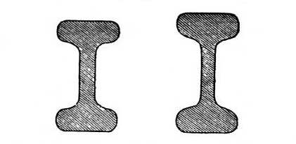
“. . . . the parallel rails laid down on
the Grand Junction, and the London and Birmingham railways. The
left hand one is sixty-four lbs. per yard on the London and
Birmingham, and sixty-two lbs. per yard on the Grand Junction. The
right hand one is the London and Birmingham seventy-five pound
rail. Rails of this kind are laid on seventy-five miles of that
railway, and were intended to be at five feet bearings, but proved a
complete failure at that distance, which had to be reduced to three
feet nine inches. The left hand one was intended to be at four feet
bearings. These rails were laid down contrary to the opinion of
the engineer, Mr. Stephenson, and have entailed a vast expense on
that company. They have wooden wedges.”
A Practical Treatise on Railways,
Explaining Their Construction, Peter LeCount (1839).
It is interesting to note in Lecount’s record of events (which
contain a hint of ‘I told you so’) that the Directors, rather
than Stephenson, were in the driving seat; but as considerable
savings in the cost of sleepers, chairs &c. and labour were to be
had by adopting a wider chair spacing, it is, perhaps, unsurprising
that on this the money men took control:
“As usual, where all was theory, there were
considerable diversities of opinion. Those who wish to enter more
at large on this subject, may consult Professor Barlow in favour of
lengthening the bearings, and Lieutenant Lecount against it. As the
matter has had a fair trial, it is only necessary here to state the
results.
On the Primrose Hill contract, which was laid with four-feet
bearings, it was found much more troublesome to keep the permanent
way in order, than with bearings of three feet. With the four-feet
bearings, it was found, that, in a very short time, the rails were
put out of gauge, the width continually increasing, until it became
absolutely necessary to readjust the whole. This was observed in a
very marked manner with a part of the line near KiIburn, which had
been recently laid down.
On the Harrow contract, from the crossing of the Harrow road to No.
12 cutting, the permanent road was used for conveying away the
material from a side cutting. The traffic was of course
considerable, but not by any means such as to account for the
absolute difficulty which the contractors had in keeping the railway
in gauge. They were obliged to put sleepers at the joints in
addition to the regular number of blocks, which of course kept the
rails in gauge at those points; but notwithstanding this, the
intermediate blocks moved outwards . . . .
On the Berkhamsted contract, where five feet bearings were in use,
and where a locomotive engine was at work, the contractors made
heavy complaints of the greater difficulty they had experienced in
keeping the rails in gauge than there was with the shorter
bearings. In fact, in the eighteen months prior to June 1837, the
three-feet rails in some parts of the line, had more work than they
now have, where the line is open; yet they stood it well, whilst the
five-feet have been so put out of gauge by one day’s work, that the
waggons had to be stopped till one and two additional sleepers for
each five feet could be laid down, and even then they were but
indifferent; and similar complaints having come in from other
quarters, together with the fact that the five-feet bearings on the
Liverpool and Manchester railway were found to cost double the sum
for keeping the way in repair that was required with three feet nine
inches bearings, the whole question had to be opened again, and
the directors resolved to shorten the bearings from five feet to
three feet nine inches.
This lateral deflection is of most serious importance, when we
recollect that the rails being out of gauge will throw the trains
off the line.”
A Practical Treatise on Railways,
Explaining Their Construction, Peter LeCount (1839). |
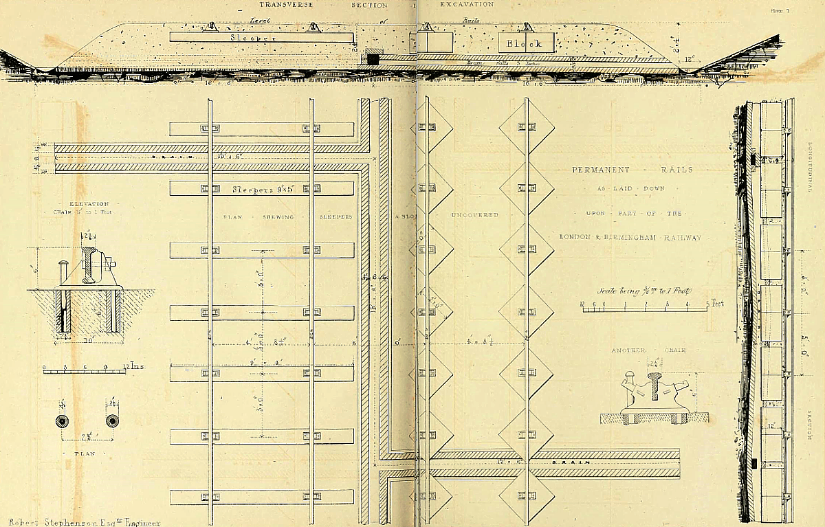
A drawing from Stephenson’s
specification for the permanent way.
Above: stone blocks (right of
drawing) were laid diagonally, instead of vertically. This was thought to have
the effect of steadying the rails,
while it gave the workmen access to the
four sides to set them right if they became displaced.
Below: detail. Chairs placed at 3 feet spacing.


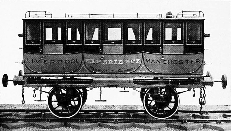
Mail coach, Liverpool & Manchester Railway.
The coach is sitting on fish-bellied rails seated on diagonally laid stone
blocks
of the pattern used on the London and Birmingham
line.
|
The following describes the London to Birmingham
track in the year in which the line was opened:
RAILS.
The total length of the line is 112½ miles. The part between Euston
Grove and Camden stations is laid with four double lines of rails;
the remainder with two double lines. The sidings, or
passing-places, with the stations, &c., make an addition of one
tenth to the quantity of the rails, so that there will be about 125
miles of double line of railway.
The width of each double line of way is five feet. The space in the
centre, between the lines, is six feet.
The rails used on the line are all of malleable iron. Those
originally laid upon the Liverpool and Manchester line were of the
weight of 35 lbs. to the yard; but they have been found insufficient
for the immense traffic, and they have accordingly been increased.
On the London and Birmingham line 10 miles are laid with rails of
unequal depth termed fish-bellied, 50lbs. to the yard; 25 miles with
parallel rails 65lbs to the yard; and the remainder with parallel
rails 75lbs to the yard.
The rails are supported by cast iron chairs or pedestals of an
average weight (of about 25lbs) fixed to stone blocks or wood
sleepers; a piece of felt being placed between each chair and
block. The chairs under the 50lbs. rails are 3 feet from centre to
centre, under the 65lbs. rails 4 feet, and under the 75lbs. rails
they were intended to have been 5 feet; but, this latter bearing
having been considered too great, has been altered to 3 feet 9
inches in the cuttings and small embankments, and to 2 feet 6 inches
on the higher embankments.
The rails are raised above the ground rather more than an inch; they
are wedged to the chairs with oak keys.
SLEEPERS.
The stone blocks under the chairs are 2 feet square and 1 foot deep,
excepting those under the joints of the 75lbs rails which are 1 foot
3 inches deep. They are laid in a direction diagonally to the
rails. The descriptions of stone are various, ― viz. Granite,
Limestone, Portland, Bramley Fall, and Whitby.
The sleepers are mostly of larch and oak, some few are of beech; all
9 feet long, 9 inches wide, and 5 inches deep.
The blocks are used in the excavations and on the smaller
embankments; the sleepers on the large embankments.
The chairs are attached to the blocks by drilling two holes in each
block, into which oak trenails, or plugs, are driven, and a spike
inserted through them and the chairs. The chairs are attached to
the sleepers by a couple of pins or spikes.
The trenails are 6 inches long, with a hole bored through for the
spike.
The ballasting of the line is about 2 feet in thickness, being 10
inches under the bottom of the blocks, and 18 inches under the
sleepers. Open brick drains, to take off the soakage, are laid
along the centre of the ballasting, and each side in the
excavations.
Where the common roads pass the railway on a level, the part of the
road between and on each side of the rails is paved with granite
carriage-way paving.
The Iron Road Book and Railway Companion,
Francis Coghlan (1838).
|
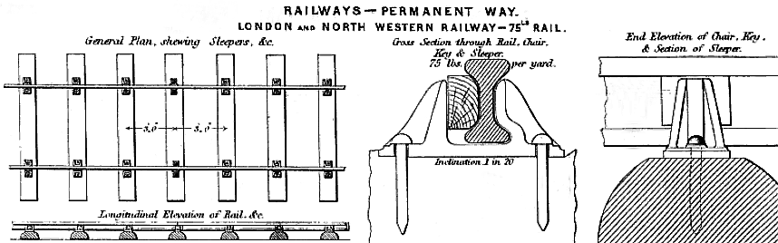
L.N.W.R. permanent way using 75lb rail,
from The Practical Railway Engineer, G. D. Dempsey (1855).
|
――――♦――――
SAFETY AND RAILWAY SIGNALLING
|
On an engine, in the
night-time,
Flying through the starlit gloom;
Not a word between us spoken:
On great caution hangs our doom.
Watch the gauge ― turn on the water ―
Ope the gleaming furnace-door,
Making us appear like demons,
In the glare, and smoke, and roar!
Ho! the signal! Put the break on!
Shut off steam ― reverse the gear!
Now the monster throbs and struggles,
While we stare ahead and fear.
To man’s frail limbs the mighty engine
Yields obedience, and we stand
Beneath the lofty danger-signal.
(Isn’t this description grand?) |
|
From Fifty years of the London
& North Western Railway,
David Stevenson (1891) |
Railway signalling and telecommunications (originally the electric
telegraph) evolved in partnership, almost from the start of the
steam worked public railway era. These two disciplines were later
to be joined by a third, digital computing. Nowadays, components
from each combine to form systems capable of providing a distant
traffic control centre with the ability to transmit instructions to
any part of the network and to receive a wealth of information on
the location of trains and on the status of track and other
equipment. By comparison, the signalling system first employed on
the London and Birmingham Railway was primitive:
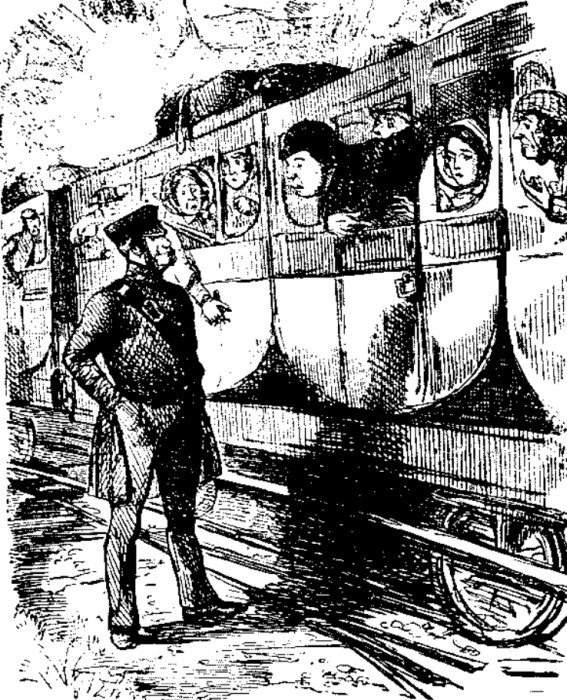
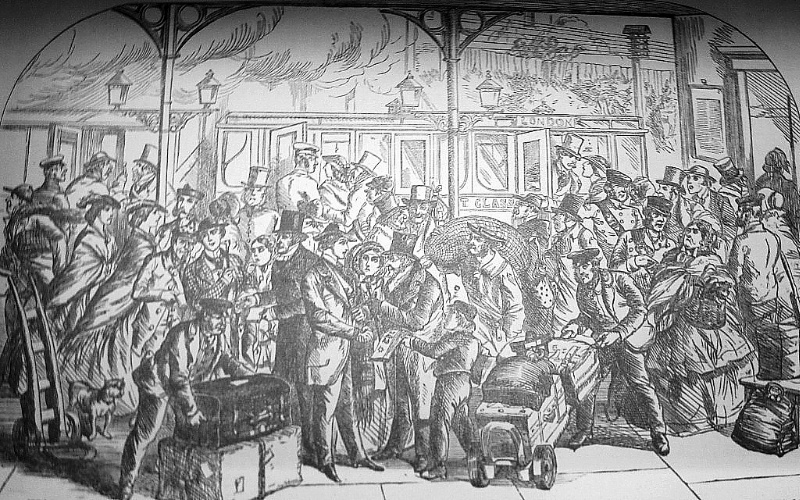
|
Passenger.
Guard.
Passenger.
Guard. |
“Whats
the matter guard?”
“Oh,
nothing particular, sir. We’ve
only run into an excursion train!”
“But,
good gracious! there's a train just behind us, isn’t
there?”
“Yes,
sir! But a boy has gone down the line with a signal,
and it’s
very likely they’ll
see it!”
From Punch (magazine) |
Until the deployment of the electric
telegraph ― which was not as quick as it might have been ― there was
no means of even monitoring the progress of a train. If it was
unduly late, all that could be done to discover why was to despatch
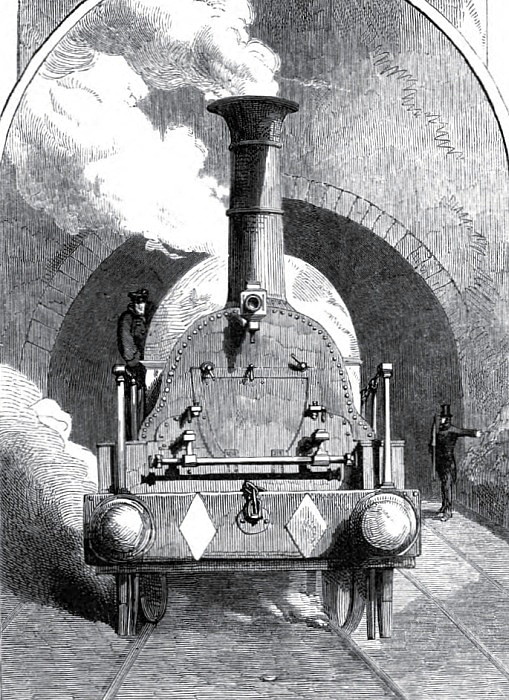
a spare locomotive (or a horse and rider) to find it. As this
section attempts to illustrate, the appearance of effective railway
safety took time ― even the introduction of the locomotive’s steam
whistle had to await a level-crossing accident. [8]
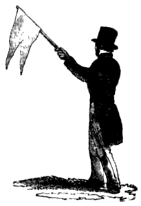
A railway policeman (right) giving the
‘all clear’.
In its bare essentials, railway signalling is designed to prevent
collisions between trains. However, an accident that occurred at
Harrow in November 1840 demonstrates another aspect to the problem,
which modern railway signalling systems control by automatically
stopping trains that pass signals set to danger. In this case the
driver of the ‘train engine’ of a double-headed goods train ignored
a stop signal, causing his train to collide with a stationary engine
with fatal consequences:
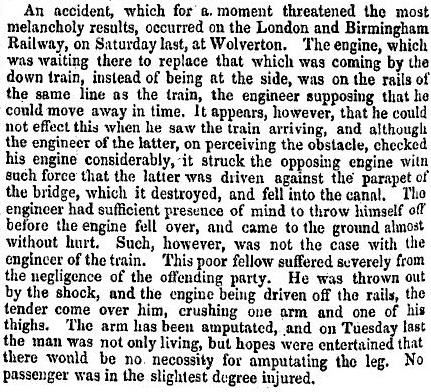
“At the inquest on the two men killed
by the collision near the Harrow station of the London and
Birmingham Railway, the evidence proved that the blame rested
principally with the driver of the second engine of the waggon
train; who did not shut off the steam, though warned; and the train
consequently ran against the engine which was standing on the line.
The man lost his life for his want of care; and the fireman of the
first engine was also killed ― he had jumped off, it is supposed,
and been run over by the waggons. The driver of the engine which
was standing on the line was also blameable for having left his
engine in the care of the stoker, whilst he went to a public-house
to obtain refreshments for the men at work in clearing the railway
from the obstruction caused by the break-down of a waggon-train in
the early part of the afternoon. It appeared from the
examination of the witnesses at this inquest, that Bradbury, the
driver of the first engine of the waggon train, cannot write his
name, or read. It was stated also that many of the men employed as
engine drivers are equally illiterate.”
From The Spectator, Volume 13 (1840).
The illiteracy that this article refers to implies a
further risk to railway safety, for being unable to read the
company’s operating instructions can negate aspects of safe working
and traffic control.
Accidents can also result from problems with the
railway infrastructure, such as a track or signalling failure: [10]
|
“The
maintenance of the permanent way in perfect efficiency
is of the utmost importance. To provide for this, the
line is divided into sections, each of about a score of
miles, to which ‘overlookers’
are appointed. These sections are subdivided into short
lengths, superintended by a foreman, or a
‘squinter’,
as he is technically designated, with two or three
assistants. The duty of the foreman is to visit his
portion of line every morning before the first train
passes, to see that the rails and sleepers are perfectly
secure, to observe whether the keys are fitted in the
chairs, and generally to inspect the fences and works.
In case of repair being required, he summons his men
to the spot, and if it is sufficient to interfere with
the passage of trains, or to warrant the exercise of
special caution on the part of engine-drivers, a
signal flag to that effect is placed eight hundred yards
above the injured spot, until the patch is completed.”
Our Iron Roads, F. S.
Williams (1852). |
 |
|
The Weekly Herald,
31st March 1839. |
|
Even the simplest of signals, such as the flag
mentioned above, by halting traffic and isolating the problem serve
to prevent matters becoming worse. Being guided by fixed rails,
railway traffic is highly vulnerable to accidents caused by line
obstruction (such as that mentioned in the Weekly Herald
article above) or track failure, particularly as trains sometimes
operate at speeds that prevent them being halted within the driver’s
line of sight.
|
 |
|
The Standard, 14th Sept.
1839 |
Thus, from the earliest days, it was recognised that
an effective signalling system together with operating rules (Appendix)
were crucial to safe railway operation. However, before describing
the railway signalling of the period, it is first necessary to say
something about the ‘policemen’ who operated the system, for their
role has changed significantly over the years.
Established in 1829, the Metropolitan Police was the U.K.’s first
police force; it was not until 1856 [11] that
county and borough police forces became compulsory throughout the
rest of England and Wales. In 1830, the Liverpool and Manchester
Railway formed a ‘police establishment who have station houses
[police stations] at intervals of about a mile along the road’.
Three years later, the London and Birmingham Railway obtained their
first Act, which required the Company to create and maintain a force
of special constables to police its property. In 1837, the
authority of the London and Birmingham force was extended to a
distance of half a mile on either side of the line:
“XXV. And be it
further enacted, That it shall be lawful for any Justice of the
Peace acting within his Jurisdiction and he is hereby required to
appoint such fit and proper Persons as he shall think proper to be
Special Constables within the said Railway and other Works and every
or any Part thereof; and every Person so appointed shall make a
solemn Declaration, to be administered by the same or any other
Justice of the Peace, duly to execute the Office of Constable for
the said Premises; and every Person so appointed, and having made
such Declaration as aforesaid, shall have Power to act as a
Constable for the Preservation of the Peace and for the Security of
Persons and Property against Felonies and other unlawful Acts within
the Limits of the said Premises, and within Half a Mile therefrom,
and shall have, use, exercise, and enjoy all such Powers,
Authorities, Protection, and Privileges for the apprehending
Offenders, as well by Night as by Day, and for doing all Acts,
Matters, and Things for the Prevention, Discovery, and Prosecution
of Felonies and other Offences, and for the Preservation of the
Peace, as Constables duly appointed now have by the Laws and
Statutes of this Kingdom; and it shall be lawful for any such
Justice to dismiss or remove any such Constable from his Office of
Constable, and upon every such Dismissal or Removal, all Powers,
Authorities, Protections, and Privileges by virtue of such
Appointment as aforesaid vested in any Person so dismissed or
removed shall wholly cease.”
An Act to amend the Acts relating to the
London and Birmingham Railway,
1 Victoriæ, cap. lxiv, R.A. 30th June
1837.
Today, points and signals are operated by signalmen,
but in the early days the railway policemen performed this task. A
railway policeman’s duties also included collecting tickets, serving
on occasions as booking clerks, and performing (on railway land) the
law enforcement duties that police perform in the community today:
|
“The
inspector at each station has a portion of these men
under his orders; they are on duty ― that is, walking
backwards and forwards on their beat ― from half an hour
before the passing of the first train in the morning
till after the passing of the last train at night. I
can vouch to their promptitude from personal knowledge,
having spoken with every man from London to Birmingham,
when I surveyed the line . . . . and I am convinced
that, were the Directors themselves placed on the line,
they could not display greater anxiety than these men do
for the protection and safety of those travelling on the
railway. Each man, besides being in the employ of
the Company, is sworn as a county constable; they
receive the same pay, and wear a dress similar to that
of the metropolitan police, except in colour which is
green. Watch boxes are placed at certain distances
on the line, to protect the men from bad weather . . . .
The principal stations at present are at Watford, Tring,
Denbigh Hall, Rugby and Coventry. At each of these
places, two clerks, a police inspector, and several
policemen and porters, are in attendance. At the
secondary stations, which are the Harrow, Boxmoor,
Berkhamsted, and Leighton Buzzard, there is but one
clerk, an inspector, and a less number of policemen and
porters.”
The Iron Road Book and Railway
Companion, Francis Coghlan (1838). |
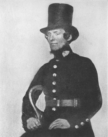
The original
Metropolitan Police uniform. London and Birmingham
Railway police were similarly attired. |
Because the London and Birmingham Railway was double-tracked
throughout, in normal operation all that was required of the
signalling system (excluding control over points and junctions) was
to ensure that trains were spaced sufficiently far apart to avoid
one train colliding with the rear of the train in front. Policemen,
stationed at intervals along the line (‘blocks’) used sand glasses
to time the interval between trains. If a train passed shortly
before the following train arrived, then the driver of the following
train was instructed to slow down or stop in order to increase the
distance between it and the train in front. This method is called
‘time interval working’, and the means by which a railway policeman
halted a train, or indicated to its driver the status of the block
he was about to enter, was by using flag signals or different
coloured lights during darkness:
“Throughout
the journey travellers will have observed a number of policemen
stationed along the Railway, who not only prevent intrusion,
but are charged with the important duty of keeping the road free of
obstruction and making signals as the train passes. The police are
placed along the line at distances varying from one to three miles,
according as local circumstances render it necessary. Each man
has his beat and duties defined, and is provided with two signal
flags, one of which is red and the other white: the white flag is
held out when no obstruction exists; and, on the contrary, the red
flag indicates that there is danger, and that the train must not
pass the signal till it is ascertained that the cause of danger is
removed.
Each policeman, also, is furnished with a revolving signal lamp, to
be used after dark; which shows, at the will of the holder, a white
light when the line is clear; a green one when it is necessary to
use caution, and the speed of the train be diminished; and a red
light, to intimate the necessity of immediately stopping. The
whole of the police department is under the able control and
superintendence of Captain C. R. Moorsom, R.N., a gentleman who has
been connected with the Company since its formation, as one of the
Secretaries. It is but justice to add, that the police arrangements
on the London and Birmingham Railway are more complete than on any
other line.”
The London and Birmingham Railway,
Roscoe and Lecount (1839).
 |
|
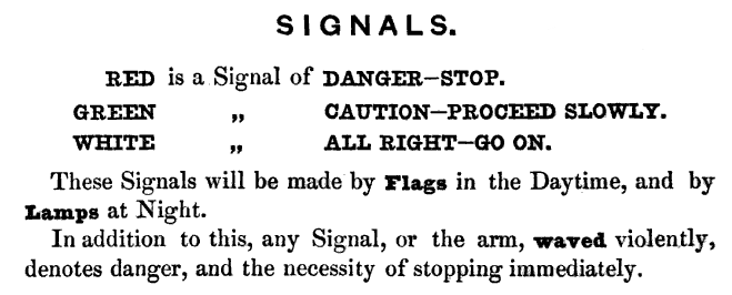
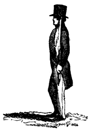
1. When the Line is clear and
nothing to impede the progress of the Train, the
Policeman on duty will stand erect, with his Flag in
hand, but show no signal thus . . . |
2. If it be necessary to proceed
with Caution the Green Flag will be elevated thus . . .
. |
3. If it be necessary to proceed
with Caution from any defect in the rails, the Green
Flag will be depressed thus . . . . |
|
 |
 |
 |
|
4. If required to stop, the Red Flag will be shown
and waved to and fro, the Policeman facing the Engine.
5. Engine-Drivers must invariably Stop on seeing the Red
Signal.
6. As soon as the Engine passes, the Policeman will
bring his flag to the shoulder.
7. Every Policeman will be responsible for having his
Hand Lamp in good order. |
|
From the London & North Western
Railway signalling rules, 1848. |
When writing about some of the problems that occupied
the Board during the early days of the Railway, David Stevenson, a
former employee, included railways signalling:
“The working
of the line went struggling towards a state of order. The rails
were found to be too light for the traffic ― 56lb fish-bellied rails
in some cases ― the stone blocks a failure; fires to luggage on the
tops of the carriages frequent; signals by flag and hand lamps
insufficient. The signalmen, dressed in police uniform, had been
drilled by Mr. Superintendent Bedford, formerly of the Guards and
lately of the Metropolitan Police, and they brought the flag-staff
round to the shoulder, as the trains passed, with true military
precision. But they were not enough, and signal posts were
contemplated. These and many other defects occupied the Board and
Management.”
Fifty years of the London & North Western
Railway,
and other memoranda in the life of
David Stevenson, (1891).
It is unclear exactly when the signals mounted on posts that
Stevenson refers to were introduced, but in the account given by
Frederick Williams (in which he also refers to flag signals) he
describes the signalling posts in use by the London and North
Western Railway a few years after its formation, but without saying
whether they were in use on the southern section (the former London
and Birmingham Railway). Nevertheless, they are indicative of the
state of railway signalling at the time:
|
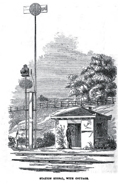
“The signal
arrangements at the intermediate stations on the
[London and]
North Western line are various, but all are simple and
complete. A station signal is provided for both the up
and the down line, one being usually erected at each end
of the station, and of the kind represented in the
Engraving. On a train stopping, or travelling slowly
through an intermediate station, the signal which is
painted red on one side is shown for five minutes in the
direction from which the train has come, in order to
stop any following train; the green signal, on the
shorter post, is then turned on for five minutes, to
complete the ten minutes precautionary signal . . . . As
the lamps and the boards are connected together, the
lamp has only to be lighted at night or in a fog, and
the arrangement is complete. When the vane is presented
edgewise to the driver of an approaching train as is
seen in the Engraving, it shows that all is right. The
higher mast supports the red signal and the lower one
with the lamp has the green.”
Our Iron Roads, F. S.
Williams (1852) |
 |
|
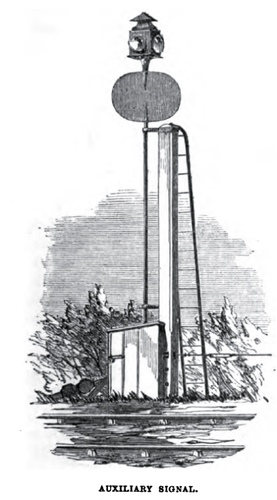 |
“Besides these there
are auxiliary signals at most of the principal stations,
worked by means of wires, which permit their being
placed at almost any distance from the spot where they
are regulated. These auxiliaries are especially
valuable in thick weather; for as they are constructed
several hundred yards up or down the line; drivers of
engines can obey them when it would be impossible for
them to see the station signals with distinctness. They
are constructed with only the green or ‘caution,’ and
the ‘all right’ signals; the presence of the former
intimating that the red signal is turned on at the
station, and that it is therefore to be approached
slowly. In the Engraving of the station signal, the
reader may observe the lever by means of which the
auxiliary signal is worked.”
Our Iron Roads, F. S.
Williams (1852) |
 |
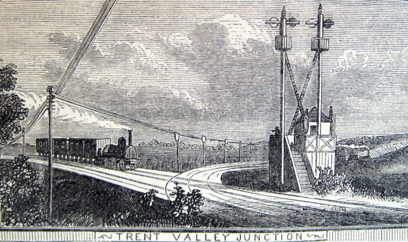
|
“Where junction lines unite, or
lines cross one another at the same level, it is
essential that a complete
system of signalling should be adopted. The Engraving .
. . . represents a junction or double signal station.
It consists of two masts, to the summits of which
fan-like arms and lamps are attached; these convey the
desired information to the drivers of approaching
trains. When the arm which is painted red, and is
always on the left of the engine-driver, is at right
angles to the mast, it signifies danger, and the train
must be immediately stopped; if it be at an angle of
forty-five degrees, caution must be observed; and if the
arm be parallel with the post, it announces the signal
all right.”
Our Iron Roads, F.
S. Williams (1852) |
 |
|
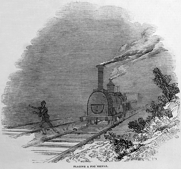
“FOG
SIGNALS. ― In foggy
weather both day and night signals are given; but in
addition, when accident or sudden emergency requires,
‘Cowper’s Fog Signal’ is used. This is a detonating
compound, packed in the shape of a small circular box,
with flanges to fasten it to the rail, and which, on a
train passing over it, explodes with a tremendous
noise. The signal thus given is the warning
immediately to stop the train. Our engraving shows
a policeman placing one in front of an advancing train.”
Illustrated London
News, 14th December 1844. |
――――♦――――
THE ELECTRIC TELEGRAPH
Separating trains using time interval working was the
best that could be achieved when the Railway first opened. However,
this method had an inherent risk ― a policeman had no way of knowing
whether a train that had passed him had in fact cleared the block.
If, for any reason, that train subsequently slowed appreciably, or
stopped, the crew of a following train had no way of knowing unless
it was clearly visible to them and at a sufficient distance
in which to bring their train to a halt. With the invention of the
electrical telegraph it became possible for policemen to exchange
messages between the ends of a block to confirm that the block was
clear and to prevent more traffic from entering if it was not. This
method is called ‘block’ working, but for many years its use was
considered an unreasonable restriction on the free flow of railway
traffic ― profit came before safety:
“The fundamental principle
of the ‘block’ was at first derided, and the name chosen was
considered as characteristic of the condition traffic was likely to
get into under any such system of working. That there should be any
reason to prevent a driver from proceeding as far as his visionary
powers assured him the line was clear, or that any train should be
prevented from ‘bumping’ a preceding train gently, of course was
considered absurd, and there were not wanting those who predicted
the early demise of this or any other system which involved
restrictions being put on the free passage of traffic. This, of
course, was before the era of express trains travelling at rates
varying between 60 and 70 miles per hour.”
Railway ‘block’ signalling, James Pigg
(1898).
|
 |
 |
|
Sir Charles Wheatstone F.R.S.
(1802-75), physicist. |
Sir William Fothergill Cooke
(1806-79), inventor. |
In the U.K., the first successful demonstration of an electric
telegraph took place on 25th July 1837, when a system developed by
William Fothergill Cooke and Charles Wheatstone was used to exchange
messages between Euston Station and the stationary engine house at
the top of the Camden Incline:
“AFTER repeated
experiments and numerous accessory discoveries of scientific men,
both in this country and abroad, the famous invention of electric
telegraphy was at length brought to the test of a fair and
satisfactory trial on the night of the 25th June, 1837, or just
thirty years ago. For the purposes of this experiment, a mile and a
quarter of telegraphic wire had been laid down between the two
stations of Euston Square and Camden Town, of what was then the new
London and Birmingham Railway. Professor Wheatstone seated in a
small ill-lit room at Euston Station, and surrounded by several men
since known to fame, and notably by Robert Stephenson, held
anxiously the one end of the mystic wire, whilst his co-adjutor, Mr.
Fothergill Cooke, attended at the other extremity in Camden Town.
We all know the result. The old inquiry: ‘Canst thou send
lightnings that they may go and say unto thee, Here we are?’ had
often been asked, and sometimes half-answered; now, however, a
positive reply was made possible; ‘Never did I feel,’ says Professor
Wheatstone, ‘such a tumultuous sensation before, as when in that
still room I heard the needles click; and as I spelled out the
words, I felt all the magnitude of the invention now proved to be
practicable beyond cavil or dispute.’ Wheatstone and all concerned
might well exult in this triumph! The telegraph has, from this
humble beginning, and within the short space of thirty years, become
an indispensable agent of civilized society.”
Telegraphic Reform ― The Post Office and
the Electric Telegraph. The Post Office (1867).
“This
instrument gives all the letters of the alphabet, the numerals, and
a vast number of conventional signals; which follow each other with
perfect distinctness at the rate about thirty five per minute, and
can be read off with the greatest facility even by an unpractised
eye.
Before the operator is placed an instrument, which gives the exact
signals which he is conveying to a distance; if therefore, through
carelessness, an error is committed, it is immediately perceived,
and corrected by the succeeding signal. These signals are
communicated from either terminus with equal facility, and literally
with the speed of lightning, both instruments being synchronous in
their action.
When the telegraph is about to be put into action, the person
communicating rings an alarm bell by striking a key, or by the same
motion he may release a weight, which can be attached to the wrist
of the person who has the working of the instrument at the distant
point. This perhaps will be the most effective mode of attracting
the attention, particularly at night, or if deaf and dumb persons
were so employed. By this simple contrivance, the unceasing
vigilance necessary for every other description of telegraphs is
dispensed with; whilst by night as well as by day, sunshine or rain,
fog or storm, the electro-magnetic telegraph performs its silent
mission, uninfluenced by those disturbing causes which render the
ordinary [i.e. optical or semaphore]
telegraph useless during four-fifths of the year.”
The London and Birmingham Railway Companion,
Arthur Freeling (1838).
|
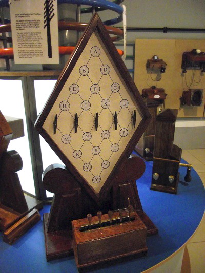 |
|
Cooke and Wheatstone indicator
panel and, below,
transmission keys. Photo: Milton Keynes Museum. |
|
 |
|
Cooke and Wheatstone’s 5-needle
telegraph.
The needles are pointing to the letter ‘G’. |
The Camden trial was followed shortly afterwards by a
radically different approach to telegraphy developed in the U.S.A.
by Samuel Morse and Alfred Vial. What became known (somewhat
unjustly to Vial) as the ‘Morse’ system, was first demonstrated on
the 11th January 1838 at the Speedwell Ironworks near Morristown,
New Jersey. It was the practicalities of this system and the Morse
Code in its various adaptations that quickly led to its universal
adoption for both line and, later, wireless telegraphy. But within
the U.K. (and throughout the British Empire) simplified versions of
the Cooke and Wheatstone system continued to be used in railway
signalling applications for many years. The system did not require
its operators to become proficient in the use of Morse Code nor to
be literate, an important factor in an age when illiteracy was
common. All that it required was for the operator to watch the left
or right deflections of a needle and/or listen to the ‘dings’ of a
signal bell.
|
“. . . .
Cooke and Wheatstone’s Telegraph still keeps its
ground. Superseded on all the principal commercial
telegraph systems, namely, those worked for the public
by the Telegraph Companies, it is still in demand for
Railway Telegraphs and other lines where simple
apparatus is required, as it is generally in the hands
of porters, brakesmen, and other inexperienced workmen.
It owes this, no doubt, as much to the character it
earned in the first stage of Telegraphic operations, as
to its simplicity and durability . . . . ”
An Illustrated Hand Book to the
Electric Telegraph, Robert Dodwell (1862). |
The history of the Cooke and Wheatstone telegraph is a study in
itself, as indeed was the complex relationship between its inventors
(reminiscent of that between Gilbert and Sullivan). Of the pair,
Cooke was the impresario with the commercial acumen and ambition who
wished to profit from the invention, and did. Professor Wheatstone
was the scientist, possessing the technical ability to deliver a
working system, the principles of which he wished to release
gratis to the world at large. Conflict between the two was
inevitable and at one stage Marc Brunel (father of I. K. B.) was
appointed to arbitrate between the collaborators over who should
receive credit for the invention ― after hearing the evidence he
distributed the honours evenly.
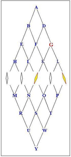
The initial design of the Cooke and Wheatstone system required for
its operation five signal wires. To transmit a character, current
was sent along two of the five wires by operating two
of five transmission keys. At the receiving station, the five
signal wires terminated on an indicator panel comprising five
needles, each of which could swivel to left or right. In the
system’s idle state all the needles pointed vertically, but when
energised by signals sent from the transmitting station, two of the
five needles swivelled to point to the letter on the indicator panel
that corresponded to that being transmitted. In the example shown
in the accompanying diagram, the two energised needles (coloured
yellow) intersect at the letter ‘G’.
The problem with the Cooke and Wheatstone system in this form lay in
the number of conductors it required. A five-wire circuit [12]
was expensive to install, added to which the limited technology of
the time gave poor electrical insulation, which quickly perished,
thereby affecting the system’s reliability. However, those who
attended the Camden demonstration ― including Robert Stephenson and
Charles Fox ― were impressed by what they saw:
“London and Birmingham Railway,
Engineering Department,
Camden Station, September 18th 1837.
My dear Sir, ― I have great pleasure in adding my testimony to that
of many others, who have been gratified by witnessing the very
beautiful experiments exhibited by yourself and Professor Wheatstone
to prove the practicability of transmitting signals by means of
electro magnetic fluid. Nothing can have been more satisfactory
than these experiments, which have placed beyond a doubt that the
principle may be applied with unerring certainty.
I am dear, Sir, yours very truly,
Charles Fox, Resident Engineer.
W.F. Cooke, Esq.”
A Reply to Mr. Cooke’s Pamphlet, ‘The Electric Telegraph . . . .’,
Wheatstone and Cooke (1855).
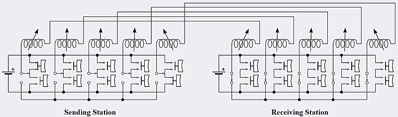
Circuit diagram of the 5-needle telegraph
transmitting the character ‘A’.
Picture:
Spinningspark
However, the Directors were only prepared to lay down
telegraph lines between London and Birmingham provided that their
counterparts at the Grand Junction Railway Company continued the
circuits northwards to Liverpool; this they refused to do. As a
result, the telegraph languished for the remainder of the Railway’s
independent existence, with signalling between the ends of the
cable-worked Camden Incline being conducted over a pneumatic system.
“The
trains were hauled from Euston to Camden by a stationary engine and
an endless rope 2½ miles long, these ropes
cost £460 each. The working of this section is described in a
paper of the time as follows:
‘As
soon as the carriages at Euston are connected with each other and
the passengers seated, the train is pushed forward by the porters to
a bridge under Wriothesley Street; here it is attached to a large
endless rope for the purpose of being drawn up an ascent on the line
to Camden Town depot, a distance of more than a mile. The
gradients of the inclined portion of the railway vary from 1 in 62
and 1 in 366.’
The starting signal from Euston to the stationary engine at
Camden was conveyed by an underground pneumatic tube, which worked a
whistle. It is interesting to note that in 1837 Cooke and
Wheatstone had carried out some successful experiments between
Euston and Camden with their electric telegraph, and were anxious to
extend it to the North, but for some reason the directors would not
consent to this, and Cooke and Wheatstone took their invention to
the Great Western Railway, where it was successfully taken up.”
The History of the London & North-Western
Railway, Wilfred L. Steele (1914).
In the meantime, that imaginative but occasionally flawed genius I.
K. Brunel also saw the possibilities of the electric telegraph. In
1838, he encouraged the Great Western Railway Company to establish a
five-needle system between Paddington and West Drayton, a distance
of 13 miles. It seems that, in the history of railway signalling,
the laurels for introducing block working using the electric
telegraph, albeit in a rudimentary form, must go to the Great
Western Railway, for . . . .
“. . . .
the germ of the present
system was brought into use between Paddington, West Drayton, and
Hanwell, on the Great Western Railway, at the instance of Cooke and
Wheatstone, as early as December, 1839. The system there brought
into operation was an adaptation of the ordinary telegraph system
the departure and arrival of trains being telegraphed, and
instructions issued to stop a second train on its arrival at any of
the telegraph stations until the arrival of the first train at the
advance station was telegraphed back. This is the earliest record
from official sources of the application of electricity to the
preservation of a space limit between successive trains on the same
line of rails.”
Railway ‘block’ signalling, James Pigg
(1898).
|
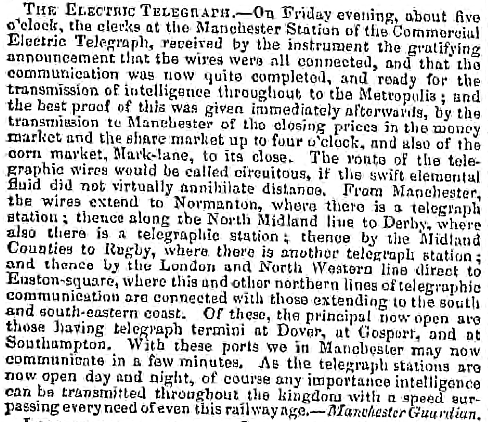 |
|
The Manchester Guardian,
20th November 1847. |
The electric telegraph did not appear on the London
and Birmingham line until after the company mergers of 1846, from
which emerged the London and North Western Railway. In the
following year telegraph circuits were laid between London and Rugby
and onwards to the north, while from Euston Square connections had
already been established with the south and south-east coasts. But
these circuits were used principally to convey revenue-earning
commercial traffic. Although the telegraph could convey messages
between stations connected to the system, signals and points were
still operated from adjacent external ground-frames, rather than
being grouped together in enclosed signal-boxes, so their operation
was physically separated from the telegraph. And so time interval
signalling continued until . . . .
“. . . . About 1855 an epoch-making change
in the matter of signalling took place on the London and
North-Western, for, about this time, the North-Western inaugurated
on the southern division [the former London and
Birmingham Railway] a
system of signalling known as the two-mile telegraph system.
Previous to this it must be confessed that almost everywhere
signalling had been in an extremely crude state, and fast travelling
in consequence fairly risky, the chief safeguard being a long time
interval between trains and a good lookout ahead.”
The History of the London & North Western
Railway, Wilfred L. Steel (1914).
|
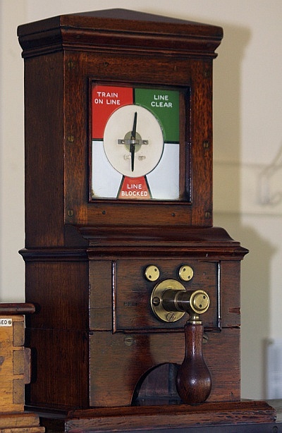 |
|
A block instrument set to its
default
position of ‘line blocked’. |
Devised by Edwin Clark, the two-mile telegraph system
was the first use on the Railway of telegraph technology that was
capable of supporting block working, the principle behind
which is to allow only one train at a time to occupy a defined
section of track, the ‘block’:
|
“Among the more recent
improvements adopted by the London and North-Western
Company for securing perfect safety of travelling over
their line, has been the establishment of a ‘special
train telegraph,’ with signal stations every two
miles. At each station a policeman is on duty night and
day, in whose watch-box there is a telegraph dial with a
single needle. By inclining the needle to the left
hand, the person in charge gives notice to the next
station that a train had passed on to the two miles of
the road entrusted to his special care; while inclining
it to the right hand would show that the train had
passed off that portion of the line. There were in fact
but two signals, ‘train on’ and ‘train
off,’ but as it might happen that an accident
occurred upon the two miles of road between the
telegraph stations, the guard and breaks-man
(sic) were
instructed instantly to sever the ‘special train
wire,’ which has the effect of placing the needle
at each adjacent station in an upright position. The
policeman on duty at once becomes aware by this movement
that something is wrong, and can act according to
circumstances.”
Civil Engineer & Architect’s
Journal, Vol. 19 (1856). |
In 1855, the system was installed between Euston Square and Rugby, a
distance of 83 miles, using 2½-mile signalling blocks. The use of
permanently flowing current along the signal wire introduced a
valuable safety feature; it kept the needles pointing to their
settings until reset. However, in other respects danger crept in,
for the principle of block working was not strictly adhered to:
“Mr.
Edwin Clark (M. Inst. C.E.) perfected the scheme of Mr. Cooke, in
the system he introduced upon the London and North Western Railway,
which was fully described. The needle instrument was employed,
but its indications were made permanent by the use of continuous
currents of electricity. It not only showed when the line was
clear, and when there was a train on the line, but also the
occurrence of an accident. This last signal was produced by
rupturing wires that descended every alternate pole on the line; but
this plan was thought to be dangerous. The London and North
Western Railway Company did not strictly adhere to the
‘block’
system. They allowed two, three, and sometimes four trains to be on
the same length at the same time. The
‘train on line’
signal was only accepted as a caution, and not as a danger signal.
This was a partial expedient, which provided a certain amount
of safety, but it was not considered sufficient under all
circumstances to prevent collision.”
The Civil Engineer and Architect’s Journal,
Volume 26 (1863).
. . . . and the system’s inventor had this to say . .
. .
“ ‘It will be
observed that in the following system it has not been thought
desirable to forbid two trains entering on the same length of line
between the signal stations, it is, however, evident, that if the
stations are placed sufficiently near together to avoid delays from
stoppages, that by such an arrangement all accidents from collisions
will be quite impossible, and in this case the caution signal will
be entirely cancelled.’
As has previously been said, the two-mile system was a great advance
on any previous signalling system, but even then absolute security
was not by any means obtained, and trains over-running one another
and collisions were not infrequent. And this state of affairs
continued until the absolute block system was afterwards adopted,
which made travelling as safe as any signalling possibly could do.”
The History of the London & North Western
Railway, Wilfred L. Steel (1914).
Following the Armagh rail disaster ― the worst in the U.K. during
the 19th Century and Ireland’s worst railway disaster ever ― [13]
the Regulation of Railways Act 1889 (52 & 53 Vict. c. 57) was
enacted and the use of the absolute block system on passenger
carrying lines became mandatory.
CHAPTER
11
――――♦――――
APPENDIX
REGULATIONS FOR ENGINEMEN
|
At a Meeting of the Board of
Directors held on the 11th of September, 1847, it was
Ordered,
That the following code of Rules and Regulations be, and
the same is hereby approved and adopted for the guidance
and instruction of the Officers and Men in the service
of the London and North-Western Railway Company, and
that all former Rules and Regulations inconsistent with
the same be cancelled.
Ordered,
That every person in the service do keep a copy of these
Regulations on his person while on duty under a penalty
of five shillings for neglect of the same.
By order of the Board of Directors.
MARK HUISH,
General Manager,
London and North Western Railway. |
1. No Engine shall pass along the wrong line of Road, but if, in
case of accident, an Engine shall be unavoidably obliged to pass
back on the wrong line, the Engineman is to send his Assistant, or
some other competent person, back a distance of not less than 800
yards, before his Engine moves, to warn any Engine coming in the
opposite direction, and the Assistant shall continue running, so as
to preserve the distance of not less than 800 yards between him and
the Engine. If dark, the man shall take his light and make a signal
by waving the same up and down, and the Engineman of the Engine
moving on the wrong line shall keep his Steam Whistle constantly
going, and must not move in the wrong direction farther than to the
nearest shunt, where he is instantly to remove his Engine off the
wrong line of Road; and it is expressly forbidden that any Engine
should move on the wrong line of Rails at a greater speed than four
miles an hour.
2. All Engines travelling on the same line shall keep
800 yards at least apart from each other, that is to say, ― the
Engine which follows shall not approach within 800 yards of the
Engine which goes before, unless expressly required.
3. No person, except the proper Engineman and Fireman shall be
allowed to ride on the Engine or Tender, without the special
permission of the Directors or one of the Chief Officers of the
Company.
4. The Engineman and Fireman must appear on duty as clean as
circumstances will allow and every Driver must be with his Engine 30
minutes, and every Fireman 45 minutes, before the time appointed for
starting, in order to see that the Engine is in proper order to go
out, has the necessary supply of coke and water, and that the
Signals are in a fit state for use.
5. The Front Buffer Light of a Passenger Train is White, and of a
Goods or Cattle Train Green, except on the Liverpool and Manchester
Section.
6. Every Engineman shall have with him at all times in his Tender
the following Tools:―
|
1 complete set of Lamps |
1 Screw Jack |
|
1 complete set of Screw Keys |
A quantity of Flax and Twine |
|
1 large and small Monkey Wrench |
4 large and small Oil Cans |
|
3 Cold Chisels |
Plugs for Tubes |
|
1 Hammer |
2 Fire Buckets |
|
1 Hammer |
Fog Signals and Red Flag |
|
2 short Chains with Hooks |
|
7. When the Engine is in motion the Engineman is to
stand where he can keep a good look out a head and the Fireman must
at all times be ready to obey the instructions of the Engineman and
assist him in keeping a look out when not otherwise engaged
8. No Engine is permitted to stand on the main line (except under
very special circumstances) when not attached to a Train, and the
Engineman shall not at any time leave his Engine or Train, or any
part thereof, on the main line, unless there be a competent man in
charge to make the necessary signals.
9. No Engine shall cross the Line of Railway at a Station without
permission.
10. An Engineman is never to leave an Engine in Steam, without
shutting the Regulator, putting the Engine out of gear, and fixing
down the Tender Break.
11. No Engine is allowed to propel a Train of Carriages or Waggons,
but must in all cases draw it, except when assisting up inclined
planes, or when required to start a train from a Station, or in case
of an Engine being disabled on the road, when the succeeding Engine
may propel the train slowly (approaching it with great caution) as
far as the next shunt or turn-out, at which place the propelling
Engine shall take the lead.
12. No Engine is to run on the Main Line Tender foremost, unless by
orders from the Locomotive Superintendent, or from unavoidable
necessity.
13. Every Engineman on going out is to take his Time Table with him,
and regulate by it the speed of his Engine, whether attached to a
Train or not; and when not attached to a Train, he is on no account
to stop at second-class Stations unless specially ordered, or there
is a signal for him to do so.
14. Enginemen are not allowed (except in case of accident or sudden
illness) to change their Engines on the Journey, nor to leave their
respective Stations, without the permission of their Superintendent.
15. When the Road is obscured by steam or smoke (owing to a burst
tube, or any other cause) no approaching Engine is allowed to pass
through the steam, until the Engineman shall have ascertained that
the road is clear; and if any Engineman perceive a Train stopping
from accident or other cause, on the road, he is immediately to
slacken his speed, so that he may pass such Train slowly, and stop
altogether if necessary, in order to ascertain the cause of the
stoppage, and report it at the next Station.
16. Where there is an accident on the opposite Line to that on which
he is moving, he is to stop all the Trains between the spot and the
next Station, and caution the respective Enginemen, and further he
is to render every assistance in his power in all cases of
difficulty.
17. In case of accident to his Engine or Tender (when alone) he is
to send back notice by his Fireman to the nearest Policeman on duty:
but if the Policeman is too distant, the Fireman is to remain
stationary not less than 600 yards in rear of his Train (until
recalled), showing his Red Signal until he has rejoined his Engine.
(See Rule 17, page 182.)
18. Enginemen are strictly prohibited from throwing out of their
Tender any small coke or dust, except into the pits made for that
purpose at first-class Stations.
19. Enginemen with Pilot or Assistant Engines must be prepared
(while on duty) to start immediately on receiving instructions from
the Locomotive Foreman or the Station Master.
20. Enginemen are strictly enjoined to start and stop their Trains
slowly, and without a jerk, which is liable to snap the couplings
and chains; and they are further warned to be careful not to shut
off their steam too suddenly (except in case of danger), so as to
cause a concussion of the carriages. ― This rule applies more
especially to Cattle Trains, the beasts being liable to be thrown
down and injured by a sudden check.
21. No Engineman is to start his Train until the proper Signal is
given: he is invariably to start with care, and to observe that he
has the whole of his Train before he gets beyond the limits of the
Station.
22. It is very important that Engine-Drivers use the utmost caution
when shunting Waggons into sidings, so as to avoid injuring the
Waggons or other property of the Company.
23. Enginemen in bringing up their Trains are to pay particular
attention to the state of the weather and the condition of the
Rails, as well as to the length of the Train: and these
circumstances must have due weight in determining when to shut off
the Steam. Stations must not be entered so rapidly as to require a
violent application of the Breaks, and any Engineman over-running
the Station will be reported.
24. Enginemen and others are required to be careful in turning their
Engines on the Tables, so as not to swing them round rapidly.
25. Engines running alone, or taking luggage or empty carriages,
must not exceed a speed of 20 miles an hour without distinct orders
in each case or some urgent necessity.
26. Enginemen and Firemen are to pay immediate attention to all
Signals, whether the cause of the Signal is known to them or not;
and any Engineman neglecting to obey a Signal is liable to immediate
dismissal from the Company’s service. The Engineman must not,
however, trust to Signals but on all occasions be vigilant and
cautious, and on no account be running before the time specified in
his Time-Table. He is also to obey the Special orders of the
Officers in charge of Stations, when required for the Company’s
service.
27. Whenever he sees the Red Signal, or any other which he
understands to be a Signal to stop, he is to bring his Engine to a
stand close to the Signal, and on no account to pass it.
28. In addition to the usual Red Signals, the Police have orders to
place Detonators on the Rails in foggy weather, and every Engineman,
when he hears a Detonating Signal, is to bring his Engine to a stand
as quickly as possible. The Enginemen also are supplied with these
Signals to be used in the same manner. (See Rule for Fog Signals.)
29. Ballast Engines are prohibited from passing along the Main Line
in a fog, except when authorised to do so under special
circumstances.
30. As a further precaution in foggy weather, no Engineman is
allowed to leave a Station with a Train until the preceding Train
has been started at least ten minutes; and before starting, the
Clerk in charge of the Station, or the Policeman on duty, is to give
the Engineman the exact time when the preceding Train started, and
where it is next to stop.
31. Enginemen are at all times to use great caution in foggy
weather, and especially in approaching Stations, from the difficulty
of discerning the regular Signals until close upon them; and they
are to be prepared to bring their Engines to a stand, should it be
required.
32. No Engineman is to pass from a Branch on to the Main Line until
the Policeman at the Junction Points signals the Main Line clear,
and in foggy weather he is to bring his Engine to a stand before
reaching the Junction Points, and not to enter upon the Main Line
till he has ascertained from the Policeman how long the preceding
Train or Engine has passed.
33. To avoid risk of collision on single Lines, from the meeting of
another Engine, no extra Engine, with or without a Train, is allowed
to pass along the Line without previous notice.
34. Every Engineman is to be careful, when he passes a Station, or
when the way is under repair, to proceed slowly and cautiously; and
he is also to do so whenever he sees the Green Signal.
35. Luggage, Coal, and Ballast Trains are always to give way to
Passenger Trains by going into the nearest siding.
36. The Whistle is to be sounded on approaching each Station and
level crossing, and on entering the Tunnels. Three short sharp
whistles, rapidly repeated, must be given when danger is
apprehended, and when it is necessary to call the attention of the
Guards to put on the Breaks. When more than one Engine is attached
to the Train, the Signal is to be given by the Leading Engineman;
and in case of danger is to be repeated by the following Enginemen,
who will forthwith reverse their Engines and attach their Tender
Breaks. Frequent use must be made of the Whistle in foggy weather.
37. Enginemen with Luggage Trains are to approach all stopping
places at a speed not exceeding ten miles an hour, when within a
quarter of a mile of the stopping place, and to signal the Breaksman
by two distinct Whistles to put on his Break before the Tender Break
is put on.
38. Luggage Enginemen must refuse to take up waggons of goods. if
they are of a nature to take fire by a spark or hot cinder; unless
such goods are completely sheeted. Enginemen are to see that the
cinder-plates at the back of their Tenders are in good order.
39. Should fire be discovered in the Train, the Steam must be
instantly shut off, and the Breaks applied, and the Train be brought
to a stand, the Signal of obstruction to the Line be made, and the
burning waggon or waggons be detached with as little delay as
possible. No attempt must ever be made to run on to the nearest
water column, if it is more than 300 yards from the place where the
fire is discovered, as such a course is likely to increase the
damage.
40. The movements of all Trains are under the orders of the Guard,
to whose instructions as to stopping, starting, &c., the Engineman
is to pay implicit attention.
41. If any part of a Train is detached when in motion, care must be
taken not to stop the Train in front before the detached part has
stopped, and it is the duty of the Guard of such detached part to
apply his Break in time to prevent a collision with the carriages in
front, in the event of their stopping.
42. Whenever a Red Board or Red Flag is carried on the last carriage
or waggon of a passing Train, it is to indicate that a Special or
Extra Train is to follow; and when such Extra Train is to run at
night, an additional Red Light must be attached to the tail of the
preceding Train.
43. Every Engineman at the end of his journey is to report to the
Superintendent of Locomotive Power, or his Foreman, or to the Clerk
in attendance
―
First ― As to the
state of his Engine and Tender.
Second ― As to any
defect in the Road or Works Electric Telegraph posts or wires or any
unusual circumstance that may have taken place on the journey.
44. He is also to see that his Signal and Gauge Lamps are taken into
the Porter’s Lodge, for the purpose of being trimmed.
――――♦――――
|
FOOTNOTES |
|
1. |
The first steel rails date from 1857. |
|
2. |
As was I. K. Brunel. On the Great
Western Railway, Brunel employed a system consisting of
bridge rails continuously supported on longitudinal
sleepers, which rested on piles driven into the trackbed.
Gauge was maintained using transverse ties. This system
remained in use for many years ― and in a modified form
continues to be used today, mainly in special
applications ― but it was gradually phased out in favour
of conventional transverse sleepers. |
|
3. |
Locke took over the role following George
Stephenson’s resignation. The Grand Junction Railway
ran for 82 miles, from Birmingham (where it shared a
terminus at Curzon Street with the London and Birmingham
Railway) via Wolverhampton, Stafford, Crewe and
Warrington, then via the existing Warrington and Newton
Railway to join the Liverpool and Manchester Railway at
Newton Junction. The line opened on the 4th July 1837;
in 1846 it amalgamated with other railways to form the
London and North Western Railway. |
|
4. |
Creosote is the portion of chemical
products obtained by the distillation of a tar that
remains heavier than water. The two main types in
industrial production are wood-tar creosote and coal-tar
creosote. The coal-tar variety, having stronger and
more toxic properties, has chiefly been used as a
preservative for wood. |
|
5. |
Some stone blocks
had been laid by George Stephenson, but were soon
replaced with wooden sleepers. |
|
6. |
Again, Locke was ahead of the game with
his constant cross-section (or parallel) bullhead rail,
which became the standard on British railways for many
years. |
|
7. |
EXPERIMENTS ON THE TRANSVERSE STRENGTH
&c. OF MALLEABLE IRON,
and
SECOND REPORT ADDRESSED TO THE
DIRECTORS AND PROPRIETORS LONDON AND BIRMINGHAM RAILWAY
COMPANY FOUNDED ON AN INSPECTION OF AND EXPERIMENTS MADE
ON THE LIVERPOOL AND MANCHESTER RAILWAY. |
|
8. |
George Stephenson
is believed to have invented the ‘steam trumpet’
(whistle) following an accident on the Leicester and
Swannington Railway, when a train hit either a cart or
herd of cows on a level crossing, and there were calls
for a better way of giving a warning. |
|
9. |
Today, a coroner’s
jury can only determine the cause of death and its
ruling does not commit a person to trial. |
|
10. |
Railway signals
fail safe ― the default position of every railway signal
is thus DANGER. |
|
11. |
The County and
Borough Police Act 1856 (19 & 20 Vict c. 69). Some
constabularies did exist before 1856 (Cheshire being an
example), but the Act made it compulsory for a police
force to be established in any county which had not
previously formed one. |
|
12. |
Some systems had a
sixth wire to increase the number of characters it could
handle. |
|
13. |
The Armagh rail
disaster, Ulster, occurred on 12th June 1889. A crowded
Sunday school excursion train had to negotiate a steep
incline, but the steam locomotive was unable to complete
the climb and the train stalled. The train crew decided
to divide the train and take forward the front portion,
leaving the rear portion on the running line; it was
inadequately braked and ran backwards down the gradient
colliding with a following train. Eighty people were
killed and 260 injured, about a third of them children.
Within 2 months of the disaster, Parliament enacted the
Regulation of Railways Act 1889, which authorised the
Board of Trade to require the use of continuous
automatic brakes on passenger railways, along with the
block system of signalling and the interlocking of all
points and signals. This is often taken as the
beginning of the modern era in U.K. railway safety. |
|
――――♦――――
|
.htm_cmp_poetic110_bnr.gif)
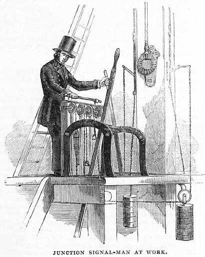