|
NOTES AND EXTRACTS
ON THE HISTORY OF THE
LONDON
& BIRMINGHAM
RAILWAY
CHAPTER 2
DEVELOPMENT OF THE STEAM
LOCOMOTIVE (I.)
THE ‘ATMOSPHERIC’ STEAM ENGINE
“Who could have credited the possibility of
a ponderous engine of iron, loaded with some hundred passengers, in
a train of carriages of corresponding magnitude, and a large
quantity of water and coal, taking flight from Manchester and
arriving at Liverpool, a distance of above thirty miles, in little
more than an hour? And yet this is a matter of daily and almost
hourly occurrence.”
The Steam Engine Explained,
Dionysius Lardner (1840).
Numerous individuals contributed to the development of the
reciprocating steam engine and to its later adaption to railway
traction, but a handful of names stand out. This chapter
summarises their contributions to the state of development that the
railway locomotive had reached at the opening of the Stockton and
Darlington Railway in 1825. Later developments are dealt with in
Chapter 12.
The first practical application of the steam engine was for pumping
water from mines. Until then, the depth at which mining could be
carried out had been restricted by the limited ability of
horse-operated equipment to drain water from the workings.
|
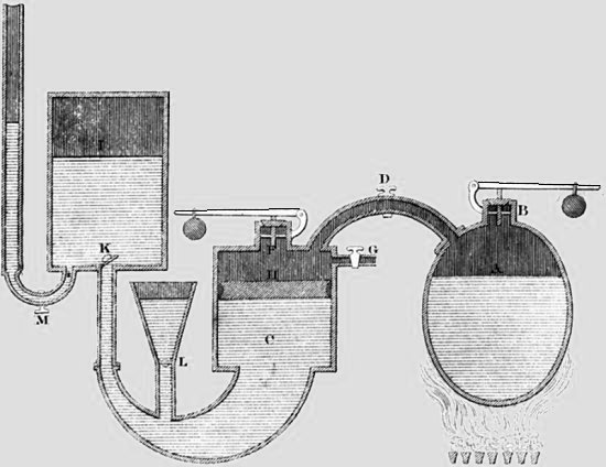
Papin’s pump of
1704.
Water enters the
system through valve L. The boiler (B) and cylinder (C)
are fitted with weighted safety-valves. When
valve D is opened, steam is admitted to the cylinder,
forcing down the piston, which drives the water beneath
it into the reservoir through valve K and in the process compressing the air
above it. The steam in
cylinder C is condensed to form a vacuum, which forces the piston
upwards, drawing more water into the system through valve L and
closing valve K. Closure of valve K removes the steam
pressure causing the water in the reservoir to be expelled
through valve M under the action of the compressed air
above it. |
|
 |
|
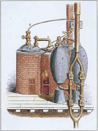
The 1698 Savery
Engine. |
The Frenchman Dionysius Papin (1647-1714) was among the early
inventors of the steam engine and to him goes the credit for being
the first to derive thrust from a piston within a cylinder. From
1690 until about 1707 ― when he published The New Art of Pumping
Water by Using Steam ― Papin built a number of steam engines
including a successful piston-operated water pump, but he did not
develop it commercially. His contemporary, Thomas Savery
(1650-1715), developed a thermic siphon ― other than valves, it had
no moving parts ― which relied on a vacuum created by condensed
steam to draw water up into a storage chamber from where, after the
operation of valves, it was expelled by steam pressure. Because Savery’s siphon lifted water by vacuum, it needed to be no more than
30 feet above the water it was to pump, which for mining operations
was impractical, while the working models are reported to have
suffered failures due the crude engineering methods of the age.
The distinction for creating the first practical steam-driven pump
goes to Thomas Newcomen (c. 1663-1729), an ironmonger from Exeter in
Devon, who succeeded in developing the ideas and techniques advanced
by Papin and Savery to develop an ‘atmospheric’ steam engine, the
earliest working example of which is believed to have entered
service at the Wheal Vor mine on the south coast of Cornwall,
although examples appear to have reached the North of England at
about the same time:
“The first steam engine erected in the north was at Oxclose, near
Washington; the next at Norwood, near Ravensworth. About the year
1713, or 1714, the first steam engine in Northumberland was erected
at Byker colliery, the property of Richard Ridley, Esq.”
An Historical, Topographical, and Descriptive View of the County of
Northumberland,
Eneas Mackenzie (1825).
|
 |
|
The Newcomen engine.
– Steam is shown pink
and water is blue.
– Valves move from open (green) to closed (red) |
The Newcomen engine comprised a reciprocating piston (as utilised by
Papin) coupled to a pump rod via a rocking beam. Steam injected into
the engine’s cylinder drove the piston upwards while the beam drove
the pump rod downwards. When the piston reached the top of its
stroke, cold water was injected into the cylinder beneath to
condense the steam. The resulting vacuum caused the piston to be
drawn back to its starting position under atmospheric pressure (as
utilised by Papin and Savery), raising the pump rod in the process. At this point the cycle was repeated.
In the Newcomen engine, the constant heating and cooling of the
cylinder wasted a great deal of heat. Nevertheless, it represented a
great advance in pumping, which enabled mining to be carried out at much
greater depths:
“Newcomen and Cawley’s [1] engines were found to answer the purpose
of raising water so well, that in a few years they were introduced
into Russia, Sweden, France, and Hungary; and about 1760 one was
imported by the proprietors of the old copper mine near Belleville,
New Jersey. They in fact imparted a new and very beneficial impulse
to mining operations, and quickly raised the value of mining stock.
Deluged works were recovered, old mines deepened, and new ones
opened in various districts, both in Great Britain and continental
Europe: nor were they confined to draining mines, but were employed
to raise water for the use of towns and cities, and even to supply
water wheels of mills.”
A Descriptive and Historical Account of Hydraulic and Other
Machines,
Thomas Ewbank (1842). |
Despite being rendered obsolete by the later developments of James
Watt, the cheapness and simplicity of Newcomen engines led to their
continued manufacture until well into the 19th Century.
――――♦――――
THE ‘DOUBLE-ACTING’ STEAM ENGINE
Watt improved the Newcomen steam engine in a number of ways.
He invented the purpose-built condenser, means to produce rotary (as opposed to
reciprocating) motion, the
centrifugal governor and the double-acting engine.
In a Newcomen-type engine, the cylinder doubled up as a condenser.
At the end of the up-stroke the steam within it was condensed to
form a vacuum ― cooling the cylinder in the process ― to draw the
piston back to its starting position. However, by exhausting
the spent steam into a separate
condenser, a vacuum was formed beneath the piston without
needing to cool the cylinder, and this significantly improved the
engine’s thermal efficiency. Watt’s development of rotary motion enabled his
engines to be used to drive factory machinery, in which context his
use of the ‘centrifugal governor’ to regulate an engine’s speed of
rotation automatically was another important advance. [2] But
Watt’s
development of greatest importance to railway traction was
the ‘double acting’ steam engine:
“In the specification of his third patent,
1782, he [Watt] says, ‘My second
improvement upon steam or fire engines consists in employing the
elastic power of the steam to force the piston upwards, and also to
press it downwards, by alternately making a vacuum above or below
the piston respectively; and at the same time employing the steam to
act upon the piston, in that end or portion of the cylinder which is
not exhausted. An engine constructed in this manner, can
perform twice the quantity of work (with a cylinder of the same
size) or exert double the power, in the same time which has hitherto
been done by any steam-engine, in which the active force of the
steam is exerted upon the piston only in one direction, whether
upwards or downwards.’”
A Treatise on the Steam Engine, John Farey (1827).
In both the Newcomen and the early Watt atmospheric engines, the
pressure of expanding steam on the piston delivered one power
stroke, while the return stroke was delivered by a vacuum formed by
condensing the spent steam. In a ‘double-acting’ steam engine, the
pressure of expanding steam is used to deliver both power strokes.
[3] This is achieved using what in effect is
a two-part cylinder; the cylinder proper contains the piston that
delivers the thrust, the adjacent ‘steam chest’ contains a sliding
valve (the ‘slide valve’), the backward and forward motion of which
is used to direct the passage of live and exhaust steam, to and from
the cylinder.
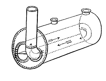
|
Two applications of the
double-acting steam engine. Above, a stationary
steam engine powering a drive belt; below, a railway
locomotive. Live steam
(pink) enters the steam chest from the boiler. A slide valve
introduces steam into the cylinder alternately through the two steam
ports. As live steam is introduced to one side of the piston, spent
steam (blue) is exhausted from the other. The slide valve is driven by an
eccentric, coupled at one end to the crank and at the other to the
valve rod. When the engine is in motion, this coupling causes the
slide valve to move back and forth, alternately covering and
exposing the steam and exhaust ports. |
Watt never attempted to apply his developments of the steam engine
to road or rail traction, but he did include that possibility in his
patent of 1784. Of this group of seven ‘new improvements’, the
second ― a method for dispensing with chains and instead connecting
the piston rod of the double-acting engine directly to the rocking
beam, to permit ‘push’ as well as ‘pull’ ― was of the most immediate
practical value. His seventh, however, came as close as Watt ever
approached the subject of traction and is interesting for its
description of his thoughts on the subject:
“My seventh new improvement is upon steam engines which are applied
to give motion to wheel carriages for removing persons or goods, or
other matters, from place to place, and in which cases the engines
themselves must be portable. Therefore, for the sake of lightness, I
make the outside of the boiler of wood, or of thin metal, strongly
secured by hoops, or otherwise, to prevent it from bursting by the
strength of the steam; and the fire is contained in a vessel of
metal within the boiler, and surrounded entirely by the water to be
heated, except at the apertures destined to admit air to the fire,
to put in the fuel, and to let out the smoke; which latter two
apertures may either be situated opposite to one another in the
sides of the boiler, or otherwise, as is found convenient; and the
aperture to admit air to the fire may be under the boiler. The form
of the boiler is not very essential, but a cylindric or globular
form is best calculated to give strength. I use cylindrical steam
vessels with pistons, as usual in other steam engines, and I employ
the elastic force of steam to give motion to these pistons, and
after it has performed its office I discharge it into the atmosphere
by a proper regulating valve, or I discharge it into a condensing
vessel made air-tight and formed of thin plates or pipes of metal,
having their outsides exposed to the wind, or to an artificial
current of air produced by a pair of bellows, or by some similar
machine wrought by the engine or by the motion of the carriage;
which vessel, by cooling and condensing part of the steam, does
partly exhaust the steam vessel, and thereby adds to the power of
the engine, and also serves to save part of the water of which the
steam was composed, and which would otherwise be lost. In some cases
I apply to this use engines with two cylinders which act alternately
. . . .”
Origin and Progress of the Mechanical Inventions of James Watt, J. Muirhead (1854).
He then goes on to describe the means by which the engine would
propel the vehicle.
Watt’s patent recognises some of the requirements that would become
essential to the later development of the steam locomotive, whether
road or rail. It states the need for lightness, and while it allows
for the use of an air-cooled condenser, both to improve engine
efficiency and to save on water consumption, its main suggestion for
handling spent steam is to exhaust it into the atmosphere; but it
seems that Watt did not imagine using exhaust steam to draw the fire
through a blast pipe. A two-cylinder configuration is also
described, which was widely adopted in the development of the
steam railway locomotive, although not at first.
Why Watt never attempted to make practical use of this proposal is a
matter of conjecture. His aversion to the use of high pressure
steam, born of the inadequate boiler technology of the age, ruled
out the development of a power plant suitable for propelling a steam
road carriage; but even if he had developed a high pressure engine,
the carriage it propelled would have had to face the further
challenge of the appalling road surfaces of the age. Watt
appears not to have considered his engine’s
use on a railway, but as events were
to prove a similar problem existed in that the cast-iron
plate rails of the time were too brittle to support the weight and
stresses created by a moving steam locomotive. As Boulton and
Watt’s business in static engines was blossoming, they probably saw
no commercial justification in undertaking the expensive research
and development necessary to develop a reliable steam road carriage
― and, as Trevithick was later to discover, there was at any rate no
market for such a vehicle.
――――♦――――
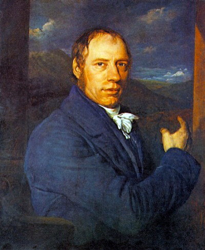
RICHARD TREVITHICK (1771-1833)
Richard Trevithick takes the honours for inventing and demonstrating the
first workable steam road and rail locomotives. However,
because there are no accurate
contemporaneous descriptions of his trials, what there is had
to be assembled years later by his son Francis, based on
correspondence and on the recollections of those who witnessed them. Unsurprisingly, the accounts so compiled are in places incomplete
and inconsistent.
|
 |
|
Richard Trevithick
(1771-1833). |
Richard Trevithick came from a family of mining engineers. Thus,
from an early age he was familiar with the Newcomen and Watt
engines used for mine drainage in his locality and by the 1790s he
was building his own.
By the end of the 18th Century, boiler engineering had reached the
stage at which the safe production of steam at a comparatively high pressure was possible. [4] This permitted
the construction of a double-acting steam engine of much smaller
dimensions than a Watt or Newcomen
engine of comparable power. Furthermore, because a high
pressure engine does not (like its low pressure counterpart) rely on
atmospheric pressure, its spent
steam could be exhausted directly into the atmosphere thereby
dispensing with the need
for a cumbersome condenser. The saving in space and weight
thus achieved made possible the use of high pressure steam engines for road and rail traction.
Unlike Watt, who had no interest, Trevithick went on to develop the
double-acting
engine for traction purposes, and while he wasn’t the first in the
field of steam road vehicles [5] he was the first to achieve
a measure of success ― albeit short-lived on
each occasion ― with his use of high pressure steam:
“Stuart, [6] writing fifty years after the date of the Watt patent,
clearly defined the difference, in principle and in practice, of the
rival engineers. Trevithick increased the steam pressure from one
atmosphere, or 14½ lbs. on the square inch, to 50 or 60 lbs., and by
it impelled the piston with four times the force of a Watt
low-pressure steam vacuum engine. Hebert, who wrote thirteen
years later, [7]
still illustrates the marked difference in the two men by pointing
out that, in 1784, Watt gave his views of a steam-carriage, and
Murdoch tried his hand at one. Watt proposed a wooden boiler,
a cylinder 7 inches in diameter, with a stroke of 1 foot, and
sun-and-planet wheels. It is not said that it was to carry
condensing water, but such may reasonably be inferred . . . .
Trevithick’s high-pressure engine, which was worked by the force of
steam 60 lbs. or more on the square inch, wholly discarded the
vacuum; and certainly without this radical change there could have
been no locomotion.”
Life of Richard Trevithick,
Francis Trevithick (1872).
|
 |
|
Replica of
Trevithick’s Puffing Devil. |
Trevithick’s first road vehicle, the Puffing Devil, emerged in 1801.
Its cylindrical cast-iron boiler produced steam at some 60 lbs per
square inch. The engine’s single cylinder was fixed within the
boiler and exhausted into the chimney, in the process heating the
boiler feed water and causing a draught through the fire. The
Puffing Devil demonstrated an ability to carry a number of
passengers up an incline, but during further testing it overturned
on the poor road surface. Eventually righted, the carriage was left
unattended while its operators retired to a nearby alehouse for
refreshment:
“The travelling engine took its departure from Camborne Church Town
for Tehidy on the 28th of December, 1801, where I was waiting to
receive it. The carriage, however, broke down, after travelling very
well, and up an ascent, in all about three or four hundred yards. The carriage was forced under some shelter, and the parties
adjourned to the hotel, and comforted their hearts with a roast
goose, and proper drinks, when, forgetful of the engine, its water
boiled away, the iron became red hot, and nothing that was
combustible remained, either of the engine or the house.”
From a letter quoted on p117, Life
of Richard Trevithick, Francis Trevithick (1872).
The Puffing Devil must have given Trevithick and Andrew
Vivian, his business
partner, sufficient encouragement to include in their
patent application for a steam-powered sugar cane crushing machine .
. . .
“Methods for improving the construction of steam engines, and the
application thereof for driving carriages, and for other purposes.”
. . . . together with a drawing of the proposed vehicle. A patent,
No. 2599, was granted on 25th March 1802.
In his biography of his father, Francis Trevithick mentions that a
further steam road carriage, the ‘Tuckingmill Locomotive’, was then
built, presumably to replace the Puffing Devil:
“Mr. Anthony Michell came to live at Redruth in November, 1802, and
shortly after, about the spring of 1803, a great many persons went
to Tuckingmill to see Captain Dick Trevithick’s puffer locomotive
that was going to run from Camborne to Redruth, about three or four
miles . . . . I could not go. They said, that in going up the Tuckingmill hill towards Redruth, the driving wheels slipped around
and sunk into the road, and they could not get her on; it was a very
steep and crooked road. Everybody was talking about it . . . .”
From a letter quoted on p120, Life
of Richard Trevithick, Francis Trevithick (1872).
What little is known about the ‘Tuckingmill Locomotive’ comes from
hearsay and from what onlookers recalled years after the event. It is
believed that the carriage performed longer journeys than its
predecessor and that Trevithick reused its engine in his London
steam carriage experiment of 1803.
Another mystery from this period is the ‘Coalbrookdale Locomotive’,
which might lay claim to being the world’s first steam railway
locomotive but for the fact that very little is known about it.
What evidence exists lies mainly in a drawing held in the Science
Museum ― which dimensional evidence suggests is of the locomotive
built at Coalbrookdale ― and in a concluding remark in a letter
written by Trevithick on the 22nd August 1802, while at
Coalbrookdale, to Davies Giddy, in which
he says that:
“The Dale [Coalbrookdale] Company have begun a carriage at their own
cost for the railroads, and are forcing it with all expedition”.
Trevithick was at Coalbrookdale to supervise construction of a
pumping engine, which he describes in his letter; it might be
that the pumping tests that he describes were of the locomotive
under static test. But there is no record of whether the “carriage”
he refers to in his letter was completed and ran successfully on
rails.
In 1803, Trevithick carried out further trails of a steam road
vehicle now generally referred to as ‘The London Locomotive’.
[8] A great improvement on predecessors, it
was lighter and its use of a horizontal rather than a vertical
cylinder, improved its steadiness while in motion, a lesson that was
forgotten by the early railway locomotive designers. Having
wheels of large diameter enabled it to pass more readily over the
poor road surfaces of the age that had brought Trevithick’s Camborne
locomotive to a standstill.
Following trials at Camborne, the engine for the London Locomotive was shipped to the Metropolis in January 1803.
The drawings that accompanied the original patent, together with a
contemporaneous artist’s impression, show the engine mounted on the
frame of a
locally assembled carriage. The body of the carriage, believed
to have been capable of accommodating eight
passengers, was mounted over the engine and boiler between the large driving wheels, and was supported on springs
fixed to the
frame.
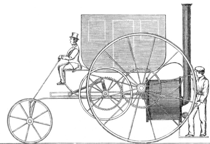
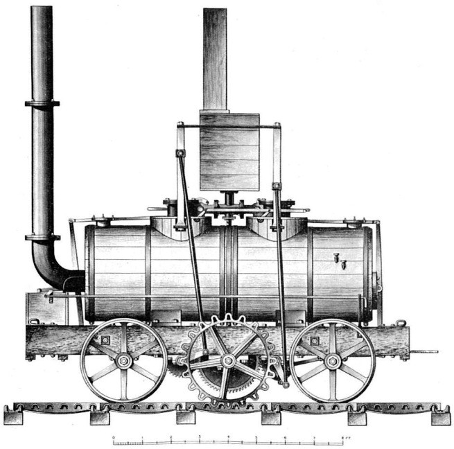
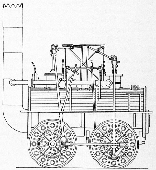
Trevithick’s ‘London Locomotive’
or ‘London Steam Carriage’ in elevation and in plan.
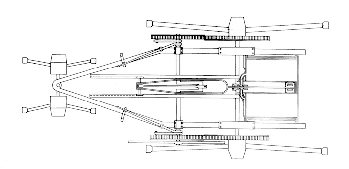
The engine and boiler were of wrought iron. The boiler had an
internal return fire-tube, which meant that the fire-door and chimney
were at the same
end (see illustration). The cylinder, fixed horizontally within the boiler,
drove a
crank placed under the carriage (a cranked axle did not appear in
railway locomotive use until the Rainhill Trials in 1829). Coal and water were carried on
the engine platform. Spent steam was directed into the chimney;
this helped draughting, thereby assisting the small boiler to produce the necessary
amount of steam.
Trials of the carriage took place on the streets of central London
on a number of occasions over several months. Writing in 1837,
Hebert says that . . . .
“There are thousands of persons now living in London who saw the
steam coaches of Messrs. Trevithick and Vivian running about the
waste ground in the vicinity of the present Bethlehem Hospital; and
likewise in the neighbourhood or site of Euston Square. This was
thirty four years ago.”
A Practical Treatise on Rail-roads
and Locomotive Engines, Luke Hebert (1837).
. . . . and 1845, Andrew Vivian’s son recalled that . . . .
“My father went to London in 1801, and again in 1802. He himself
worked the engine when it ran from Leather Lane, from the shop of
Mr. Felton (who built the carriage, and he and his sons were with
the engine all the first day it ran), through Liquorpond Street,
into Gray’s Inn Lane, by Lord’s Cricket Ground, to Paddington and
Islington, and back to Leather Lane.”
. . . . and speaking in 1860, a shopkeeper remembered seeing . . . .
“Mr. Trevithick’s steam-carriage go through Oxford Street; the shops
were closed, and numbers of persons were waving handkerchiefs from
the houses; no horses or carriages were allowed in the street during
the trial. The carriage moved along very quickly, and there was
great cheering. At that time she kept a shop next door to the
Pantheon, and it, like the others, was closed.”
But despite its apparent success, the steam carriage attracted no
commercial interest and the trials, which were proving expensive,
came to an end. The steam carriage was sold for what it
would fetch, its engine eventually powering a rolling-mill.
During this period, Trevithick had been building high-pressure steam
engines for industrial use, one of which, a forge engine, had been
installed to drive hammers at the at the Pen-y-Darren Ironworks at
Merthyr Tydfil in South Wales. This was to become the setting for the
world’s first recorded locomotive-hauled train. Rees Jones, the works’
engine fitter, helped Trevithick with the installation after which
construction began on a railway locomotive. Jones later recalled that he
helped with the assembly using components manufactured on site, but
other sources claim that some parts were manufactured in Cornwall.
The story now took a interesting turn. Samuel Homfray, the
proprietor of the Pen-y-Darren Ironworks, while discussing the
principles and feasibility of locomotive haulage with Richard
Crawshay, ironmaster of the nearby Cyfartha Ironworks, entered into
a 1,000 guinea [9] wager with him that he could
not convey a load of
iron along the Merthyr Tydfil tram-road, from Pen-y-Darren to Abercynon, a distance of 9¾ miles. Whether the bet led to the
locomotive’s construction or was made while this was in progress, is
unclear; suffice it to say that a great deal of money was at stake
on the outcome of the venture.
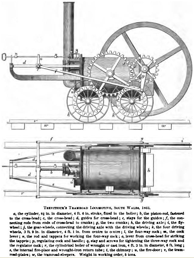
There are conflicting descriptions of the locomotive, but
according to Jones, who was on the spot ― albeit writing 54-years
after the event . . . .
“The boiler was made of wrought iron, having a breeches tube also of
wrought iron, in which was the fire. The pressure of steam used was
about 40 lbs. to the inch. The cylinder was horizontal; it was fixed
in the end of the boiler. The diameter of the cylinder was about 4¾
inches. The three-way cock was used as a valve. The engine had four
wheels. These wheels were smooth; they were coupled by cog-wheels. There was no rack-work on the road; the engine progressed simply by
the adhesion of the wheels. The steam from the cylinder was
discharged into the stack.”
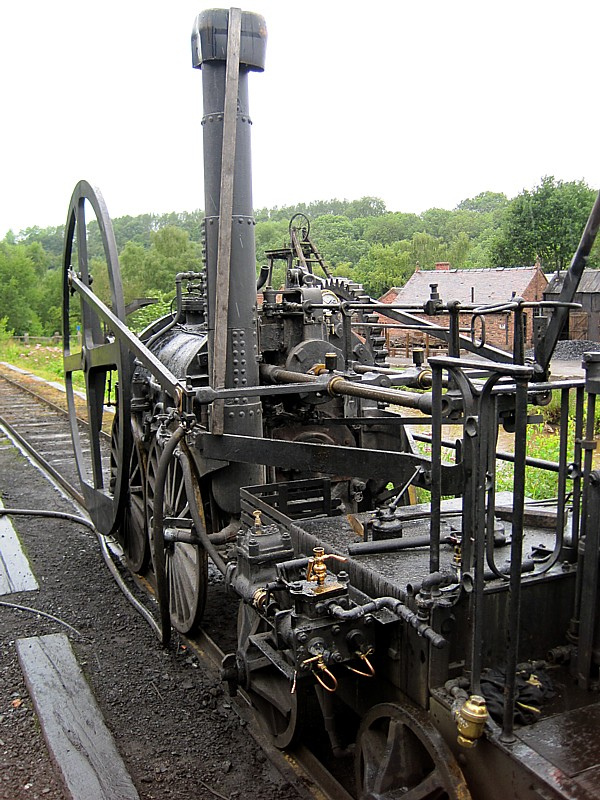
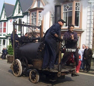
A replica of Trevithick’s
Pen-y-Darren ‘tram-waggon’ at Blists Hill,
Ironbridge Gorge Museum.
Rees Jones goes on to confirm that the locomotive ran well, a point
taken up by Trevithick in a letter dated 15th February 1804, in
which he informed Davies Giddy that . . . .
“. . . . we lighted the fire in the tram-waggon, and worked it
without the wheels to try the engine. On Monday we put it on the tramroad. It worked very well, and ran up hill and down with great
ease, and was very manageable. We had plenty of steam and power. I
expect to work it again to-morrow. . . .”
. . . . and a few days later . . . .
“The tram-waggon has been at work several times. It works
exceedingly well, and is much more manageable than horses. We have
not tried to draw more than 10 tons at a time, but I doubt not we
could draw 40 tons at a time very well; 10 tons stand no chance at
all with it. We have been but two miles on the road and back again,
and shall not go farther until Mr. Homfray comes home.”
There is no definitive account of the event, those that
exist being written some years later. In 1812, Trevithick set down
his recollections:
“About six years since I turned my thoughts to this subject, and
made a travelling steam-engine at my own expense, to try the
experiment. I chained four waggons to the engine, each loaded with
2½ tons of iron, besides seventy men riding in the waggons, making
altogether about 25 tons, and drew it on the road from Merthyr to
the Quaker’s Yard, in South Wales, a distance of 9¾ miles, at the
rate of four miles per hour, without the assistance of either man or
beast; and then without the load drove the engine on the road
sixteen miles per hour. I thought this experiment showed to the
public quite enough to recommend it to general use; but though a
thing that promised to be of so much consequence, has so far
remained buried, which discourages me from again trying its practice
at my own expense.”
From the Life of Richard
Trevithick, Francis Trevithick (1872).
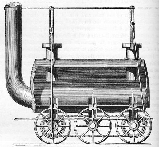
|
 |
|
The Gateshead
locomotive. The piston is at the opposite
end
to the Pen-y-Darren ‘tram-waggon’. |
The outcome of the experiment ― which is what it proved to be ― was that Homfray won the wager. But although Trevithick’s locomotive
succeeded within its limitations, it was too heavy for the tram-road
to which it caused considerable damage, and it spent the remainder of
its days employed in a static role.
It is unclear how many railway locomotives Trevithick built
following the Merthyr experiment. In 1805, he speaks of
visiting Newcastle to see “some of the travelling engines at work”,
while Wood talks of a locomotive being sent there, but without
stating when:
“The engine erected by Mr Trevithick had one cylinder only, and a
fly wheel, to secure a rotatory motion in the crank at the end of
each stroke. An engine of this kind was sent to the North for Mr Blackett, of Wylam, but was, for some cause or other, never used
upon his Rail-road, but applied to blow a cupola at an iron foundry
in Newcastle. Mr Blackett however had, in 1813, an engine of this
kind made, and set upon his Rail-road, which worked by the adhesion
of its wheels upon the rails. Still the supposed want of adhesion
formed the great obstacle to their introduction, and the attention
of engineers was directed to obtain a substitute for this supposed
defect”.
A Practical Treatise on Rail-roads,
Nicholas Wood (1825).
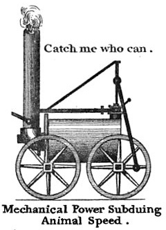
|
 |
|
A replica of
Catch-me-who-can. |
Whether a Trevithick locomotive was sent to Newcastle at this time
is doubtful; what is less so, is that an example that drew on
Trevithick’s design was constructed at Gateshead by John Steel, who
had worked on the assembly of the ‘Pen-y-Darren Locomotive’.
For some reason this locomotive did not enter service, but among the
many who came to see it on trial were George Stephenson and Timothy
Hackworth, each of whom left their mark on the development of the
steam railway locomotive.
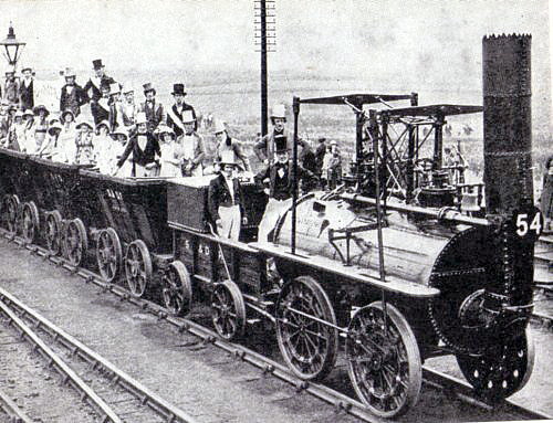
Trevithick’s last railway locomotive, of which there is a reliable
record, was constructed in 1808 for exhibition in London where it hauled a passenger carriage around a circular track
making it the world’s first passenger engine. In a letter to
Davies Gilbert, dated 28th
July 1808, Trevithick spoke of having
constructed a line on which he ran an 8-ton locomotive that had been named
Catch-me-who-can by
Gilbert’s sister. But the ground would
not support the locomotive’s weight, which also damaged the rails, and
the entire track had to be re-laid.
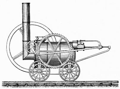
The only existing drawing of Catch-me-who-can (shown below) appears on a card or admission ticket to Trevithick’s ‘Steam
Circus’. Judging by it, the locomotive that Trevithick constructed
for this venture was a considerable step forward over that he
designed for Pen-y-Darren. The horizontal cylinder, flywheel, and geared
drive of the Pen-y-Darren locomotive are replaced by a vertical
cylinder ― still encased within the boiler ― driving one pair of
wheels directly by means of connecting rods. The boiler was
Trevithick’s usual return-flue type with an internal firebox.
The locomotive and its primitive passenger carriage were
built by John Urpeth Rastrick (whose name appears later) at the
Hazeldine Foundry at Bridgnorth.
Trevithick’s circular railway is
described in the following letter, published in the Mechanics’
Magazine, 27th March 1847:
“Observing that it is stated in your last number (No. 1232, dated
the 20th instant, page 269), under the head of ‘Twenty-one Years’
Retrospect of the Railway System’, that the greatest speed of
Trevithick’s engine was five miles an hour, I think it due to the
memory of that extraordinary man to declare that about the year 1808
he laid down a circular railway in a field adjoining the New Road,
near or at the spot now forming the southern half of Euston Square;
that he placed a locomotive engine, weighing about 10 tons, on that
railway — on which I rode, with my watch in hand — at the rate of
twelve miles an hour; that Mr. Trevithick then gave his opinion that
it would go twenty miles an hour, or more, on a straight railway;
that the engine was exhibited at one shilling admittance, including
a ride for the few who were not too timid; that it ran for some
weeks, when a rail broke and occasioned the engine to fly off in a
tangent and overturn, the ground being very soft at the time.
Mr. Trevithick having expended all his means in erecting the works
and enclosure, and the shillings not having come in fast enough to
pay current expenses, the engine was not again set on the rail.”
John Isaac Hawkins, Civil Engineer.
With this speculative venture proving unsuccessful, Trevithick’s contributions to the development of the steam
railway locomotive was almost at an end ― his final contribution,
made some years later, is described in
Chapter 12. Other than being the first engineer to employ
high pressure steam generated within a cylindrical boiler, his use
of the engine’s exhaust to draw the fire and, in his earlier
designs, coupling the
locomotive’s driving wheels, were both to become common practice in steam
locomotive design. Overall, Trevithick proved that the steam railway
locomotive was a viable proposition, an outcome that would inspire
others.
Richard Trevithick died penniless, of pneumonia, at Dartford on the 22nd April
1833. Those he had been working with contributed
towards his funeral expenses and acted as his pall bearers.
――――♦――――
IN THE WAKE OF TREVITHICK
In the period immediately following Catch-me-who-can, little interest was shown
in taking Trevithick’s experiments forward, with one exception.
The inflationary
pressure of the Napoleonic War was driving up the cost of animal
feed and with it the cost of conveying coal in horse-drawn wagons from the mines in the
North of England to the staithes [10] for shipping.
Thus, the next phase of development was driven by a search for
economy, which
prompted Christopher Blackett, owner of the Wylam Colliery near
Newcastle-upon-Tyne, to invite Trevithick to construct a locomotive
for use on the colliery’s wagonway:
“Among the charges, rendered so onerous by the war, to which the
colliery at that time was subjected, by far the heaviest was
incurred in conveying the mineral to the river, which pressed
heavily upon the undertaking as a profitable investment. Economy in
the conveyance of coal became therefore an object of primary
importance . . . . Mr. Blackett, in the year 1809, wrote to the
celebrated Trevithick on the subject of an engine; his reply stated
that he was engaged in other pursuits, and having declined the
business he could render no assistance . . . . Mr. Blackett, at a
period subsequent to his communication with Trevithick, applied to
the most eminent engineers of the day, by whom he was told that the
idea of an engine to convey carriages along a line of railroad was
chimerical, and that to carry it out was physically impossible. The
fate of the locomotive engine in South Wales was quoted as
establishing the fact. The matter was considered quite hopeless.”
Who Invented the Locomotive Engine? Oswald Dodd
Hedley (1858).
And so development of the railway locomotive languished until, in
1811, interest was reawakened. But in one respect the next phase
took a
retrograde step, for it was generally believed ― without any basis
in fact ― that the low friction between a locomotive’s smooth iron driving wheels
and the equally smooth surface of the rails would prevent the wheels
from gripping, consequently a locomotive would be unable to haul a
useful payload. The outcome was that much effort was spent
in finding a solution to this exaggerated problem.
Against this background, the next steam locomotive to emerge was at
the Middleton collieries at Leeds:
“We believe we are correct in assigning to Mr. Trevithick, of
Cornwall, the honour of first applying the steam engine to the
propelling of loaded waggons on railways; his scheme was improved
upon by Mr. John Blenkinsop, manager of the collieries at Middleton,
near Leeds, belonging to the late Charles Brandling, Esquire, of
Gosforth House, Northumberland, who obtained a patent for the
construction of the railway, and the steam carriage thereon, which
he immediately put in practice on the road from Middleton to the
coal staith at Leeds, a distance of about four miles, on which road
the coals for supplying that town are daily conveyed by steam. Since
his application of the principle, most of our eminent engineers have
turned their attention to the subject, and the consequence is, that
in a few years we may expect travelling in steam carriages to be of
as common occurrence as the conveyance of coal by the same means is
now.”
Historical Account of the
Navigable Rivers, Canals, and Railways, etc. Joseph Priestley
(1831).
The colliery manager, John Blenkinsop, knew of Trevithick’s
experiments and decided to try a steam locomotive on the colliery
wagonway. [11] Trevithick’s railway experiments had been marred by
the tendency of the brittle cast-iron plate rails to break under his
locomotive’s weight. Thus, the challenge for Blenkinsop was to
construct a locomotive light enough to run on cast-iron rails
without damaging them, but of sufficient
adhesive weight to haul a useful payload without slipping.
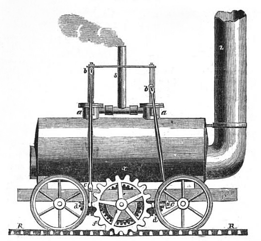
Blenkinsop and Murray’s
Salamanca.
Together with Matthew Murray, a partner in the engineering firm of
Fenton, Murray and Wood, Blenkinsop constructed a locomotive that exploited
a patent that he had taken out for a ‘rack-and-pinion’ system. [12]
Salamanca,
[13] the name given to the locomotive that emerged from Murray’s works, advanced Trevithick’s work by employing a twin-cylinder drive,
but instead of the cylinders being coupled to the driving wheels
they drove a cog, the teeth of which engaged with a toothed rack
fitted to the outside of one of the rails. In this way Blenkinsop
ensured that his engine would not lose adhesion. His boiler had a
single flu, the engine’s spent steam being exhausted directly into the
atmosphere via a flue mounted on top of the boiler
barrel. This departed from Trevithick’s scheme of directing
exhaust steam into the chimney, where the draught so created helped
to draw the fire.
On the 24th June 1812, a public trial took place of what became the
world’s first commercially viable steam railway (see also the press report at Appendix I.):
“On Wednesday last a highly interesting experiment was made with a
Machine, constructed by Messrs. Fenton, Murray and Wood, of this
place, under the direction of Mr. ― BLENKINSOP, the Patentee, for
the purpose of substituting the agency of steam for the use of
horses in the conveyance of coals on the Iron-rail-way from the
mines of J. C. Brandling, Esq. at Middleton, to Leeds. The machine
is, in fact, a steam engine of four horses’ power, which, with the
assistance of cranks turning a cog-wheel, and iron cogs placed at
one side of the rail-way, is capable of moving, when lightly loaded,
at the speed of ten miles an hour. At four o’clock in the afternoon,
the machine ran from the Coal-staith to the top of Hunslet Moor,
where six, afterwards eight waggons of coals, each weighing 3¼ tons,
were hooked to the back part. With this immense weight, to which, as
it approached the town, was super-added about 50 of the spectators
mounted upon the waggons, it set off on its return to the Coal-staith,
and performed the journey, a distance of about a mile and a half,
principally on the dead level, in 23 minutes, without the slightest
accident.
The experiment, which was witnessed by thousands of spectators, was
crowned with complete success; and when it is considered that this
invention is applicable to all rail-roads, and that upon the works
of Mr. Brandling alone, the use of 50 horses will be dispensed with,
and the corn necessary for the consumption of, at least, 200 men
saved, we cannot forbear to hail the invention as of vast public
utility, and to rank the inventor amongst the benefactors of his
country.”
Leeds Mercury, 27th June 1812.
Murray went on to build three further locomotives of the type, one
of which subsequently worked on Tyneside where it was seen by George
Stephenson, who used it as the model for his own adhesion
locomotive, Blücher, [14] and another
suffered a catastrophic boiler failure:
“We lament to state that the steam-impelled engine of J. C.
Brandling, Esq. employed on the rail-way of his colliery near Leeds,
exploded about five o’clock on Saturday afternoon. We regret to add,
that the engineer is literally blown to pieces. Several children who
were near the place have been severely scalded, but we believe that
no other life has been lost on this melancholy occasion.”
Morning Post, 3rd March 1818.
Two further approaches to solving the imagined adhesion problem
appear ― to modern eyes at least ― unconventional. That
advanced by Chapman has a present-day descendent in the ‘chain ferry’:
“In December, 1812, Messrs. William and Edward Chapman obtained a
patent for a mode of effecting the loco-motion of the engine by
means of a chain stretched along the middle of the Rail-road, the
whole length, properly secured at each end and at proper intervals. This chain was made to wind partly round, or to pass over, a grooved
wheel, turned by the engine, of such a form that the wheel could not
turn round without causing the chain to pass along with it. When
this wheel was turned round by the engine, as the chain was fastened
firmly at the end, it could not be drawn forwards by the wheel, the
carriage was therefore moved forward in the line of the chain. The
carriages containing the goods were attached to the engine carriage,
and thus conveyed along the Rail-road.”
A Practical Treatise on Rail-roads,
Nicholas Wood (1825).
In effect, the Chapman locomotive put in reverse the use of
cable-haulage by a stationary steam engine, a system later used at,
among other places,
the Stockton and Darlington Railway and the Euston to Camden incline of the London and Birmingham Railway. Tried out at Heaton and Lambton collieries, according to
Nicholas Wood “it
was soon abandoned; the great friction, by the use of the chain,
would operate considerably against it, and also its liability to get
out of order”.
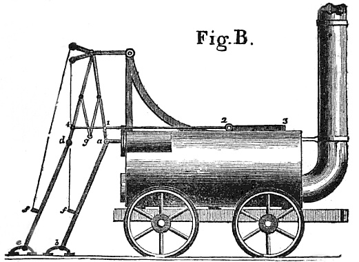
Brunton’s
‘Mechanical
Traveller’ of 1813.
A number of inventions appeared at this time that were designed to
be pushed along by mechanically operated legs. One example was
William Brunton’s
‘Mechanical
Traveller’, which to a contemporary
writer appeared to be “a machine of great singularity”.
Surprisingly, perhaps, there is evidence that the locomotive
actually worked, but its boiler exploded killing 13
onlookers and ending its trials.
Setting aside eccentric solutions to this imagined problem,
a locomotive appeared in 1813 that was capable of hauling a useful
payload without the need for rack and pinion, chain haulage,
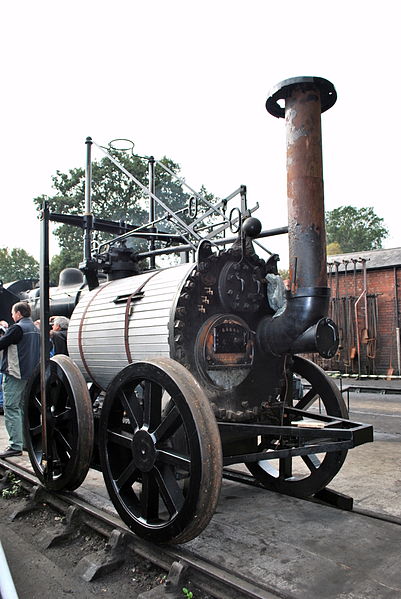
mechanical legs or any aid to adhesion other than its own weight. Commissioned by Cristopher Blackett, owner of the previously
mentioned Wylam Colliery, the design of the world’s first practical
adhesion steam locomotive, Puffing Billy, was
based on experimental data:
“Hitherto . . . . the only feasible scheme of obtaining effectual
locomotion seemed to be the procuring some fulcrum, as it were, upon
which to operate with steam, or to propel by rack work, pulling, or
thrusting. To operate by mere friction or gravity had not as yet
occurred to any one, until the late William Hedley, Esq., Viewer,
who had the direction of Wylam Colliery, conceived the idea and
having satisfied himself by a variety of experiments with the waggon-way
carriages, he took out a patent for the invention, which bears date
March 13th, 1813. The experiments were made by men placed upon the
carriages, and working the teeth gear by means of handles. The
weight of the carriage, and the number of waggons drawn after it
varied, but came to corresponding results, which were decisive of
the fact, that the friction of the wheels of an engine carriage upon
the rails was sufficient to enable it to draw a train of loaded
waggons. So conclusive were the experiments, that an engine was
immediately constructed.”
Who Invented the Locomotive
Engine? Oswald Dodd Hedley (1858).
The locomotive was built by Blackett’s manager, William Hedley, assisted by the
colliery’s enginewright Jonathan Forster and blacksmith Timothy
Hackworth. [15] As with other locomotives of
its era,
Puffing Billy
was really a stationary beam engine mounted upon a suspensionless
carriage. Hedley used two externally mounted vertical cylinders
― in itself a step forward ― to drive a single crank-shaft connected
to the driving wheels through gearing. Steam was produced in a
cylindrical boiler working at 50 lbs per sq. in., which, as was
typical of the return-flue type, was fired
from the chimney-end of the locomotive, the driver being
stationed at the opposite end of the boiler facing the fireman.
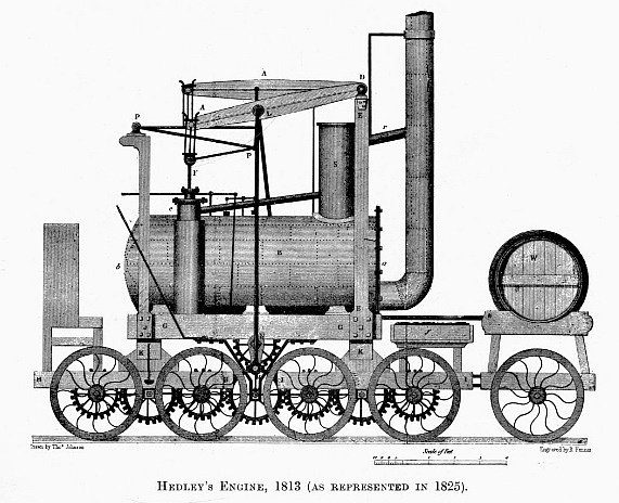
In its original four-wheeled form, the locomotive proved too heavy
for the colliery’s cast-iron plateway, which it damaged. To remedy
this, Puffing Billy was rebuilt with four axles (as shown
above) to reduce its axle weight. Later in her career, when the plateway was replaced with wrought
iron edge rails, she was returned to four flanged driving
wheels and in this form remained in service until withdrawn in 1862. Two further
locomotives, Wylam Dilly and Lady Mary, were later built to broadly
the same design: [16]
“On the Killingworth railroad locomotive engines are used. One of
these engines, it is stated, draws twelve waggons at the rate of
four miles an hour for twelve hours each day. The locomotive
machines on Wylam rail-road travel with nine waggons at a much
quicker pace. A stranger is naturally struck with the imposing
appearance of an engine moving without animal power, with celerity
and majesty, along a road with a number of loaded carriages in its
train. The coal waggon, which is formed like an inverted prismoid,
is moved on four wheels of cast-iron, and has a false bottom hung
with hinges, and fastened by a hasp. When the waggon has arrived at
the staith, the hasp is knocked out, and the coals fall into a spout
below, which conveys them into the ships or keels, or into a
storehouse underneath.”
An Historical, Topographical, and Descriptive View of the County of
Northumberland,
Eneas Mackenzie (1825).
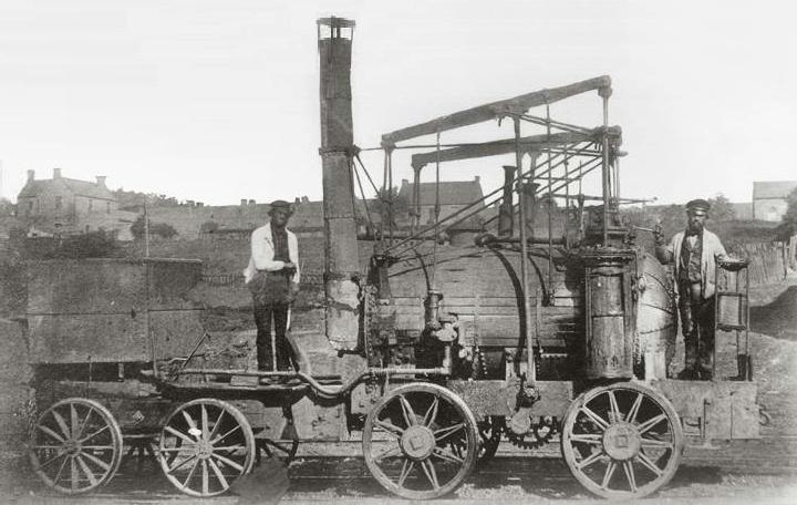
Puffing Billy
still at work in 1862.
Note the fireman and driver stationed at
opposite ends of the return flue boiler.
――――♦――――
GEORGE STEPHENSON
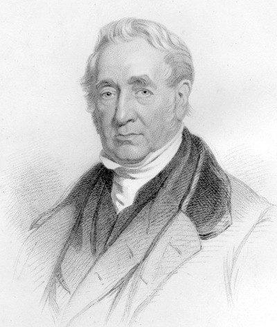
George Stephenson (1781-1848),
civil and mechanical engineer.
Having watched the progress of the Wylam locomotives, George
Stephenson suggested to the owners of the Killingworth Colliery that
they would benefit
from the use of steam traction:
“In the early part of the year 1814, an engine was constructed at
Killingworth Colliery, by Mr. George Stephenson, and on the 25th
July, 1814, was tried upon that Rail-road. This engine had two
cylinders each eight inches diameter, and two feet stroke; the
boiler was circular, eight feet long, and thirty-four inches
diameter; the tube twenty inches diameter, passing through the
boiler . . . . This engine was tried upon the Killingworth Colliery
Rail-road, July 27, 1814, upon a piece of road with the edge rail,
ascending about one yard in four hundred and fifty, to draw after
it, exclusive of its own weight, eight loaded carriages, weighing
altogether about thirty tons, at the rate of four miles an hour;
and, after that time, continued regularly at work.”
A Practical Treatise on Rail-roads,
Nicholas Wood (1825).
Named Blücher, after the Prussian general, and built in the colliery workshops
under Stephenson’s direction, the locomotive had four smooth flanged driving wheels of 3 feet
diameter. These were driven by two vertical in-line cylinders of 8
inches bore by 24 inches stroke, which were semi-immersed in the boiler
at opposite ends. As in the Hedley locomotive, the piston-rods were connected
to the wheels through a system of crossheads, coupling rods,
crankshafts and gearing. The wrought iron boiler ― 8 feet long by 34 inches in
diameter ― contained a single 20-inch diameter
flue, at one of which was the fireplace and at the other a 20-inch diameter
chimney.
The locomotive proved capable of hauling a 30-ton train at a speed
of 4 mph up a gradient of 1 in 450, but the geared transmission
produced a noisy and spasmodic motion. By exhausting the waste steam through
the chimney rather than directly into the atmosphere, the boiler’s
steam-raising ability was improved, but the geared transmission
was unsuccessful. In service, the expected
savings failed to materialise and the locomotive was dismantled, its parts
being recycled.
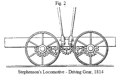
Stephenson’s next locomotive was built in collaboration with the
colliery overseer, Ralph Dodds, in 1815. In it,
Stephenson replaced its predecessor’s
geared transmission with direct drive, the front and rears pistons
being connected to the front and rear axles with coupling rods,
which, in effect, formed cranks. To ensure that the front and rear cranks
remained at an angle of 90 degrees to each other, [17] the axles
were coupled using a chain drive, for which the pair applied for and were
granted a patent (summary at Appendix
II.).
A Stephenson locomotive showing
chain coupling and
‘steam spring’ suspension.
Stephenson’s final locomotive for Killingworth dates from 1816. In its
design his attention was directed towards distributing the
locomotive’s weight evenly over its wheels using some form of
suspension, a feature he had not provided previously. This need
arose from the poor condition of the colliery wagonways whose
uneven surfaces caused constant jolting resulting in much wear and
tear, while the weight of
the swaying locomotive, distributed unevenly over its driving wheels,
damaged the lightly laid rails. Derailments were not
uncommon:
“In order to avoid the dangers arising from this cause, Mr.
Stephenson contrived his Steam Springs. He so arranged the boiler of
his new patent locomotive that it was supported upon the frame of
the engine by four cylinders, which opened into the interior of the
boiler. These cylinders were occupied by pistons with rods, which
passed downwards and pressed upon the upper side of the axles. The
cylinders opening into the interior of the boiler, allowed the
pressure of steam to be applied to the upper side of the piston; and
that pressure being nearly equivalent to one fourth of the weight of
the engine, each axle, whatever might be it position, had at all
times nearly the same amount of weight to bear and consequently the
entire weight was at all times pretty equally distributed amongst
the four wheels of the locomotive. Thus the four floating pistons
were ingeniously made to serve the purpose of springs in equalising
the weight, and in softening the jerks of the machine; the weight of
which, it must also be observed, had been increased, on a road
originally calculated to bear a considerably lighter description of
carriage. This mode of supporting the engine remained in use until
the progress of spring making had so far advanced that steel springs
could be manufactured of sufficient strength to be used in
locomotives.”
The Life of George Stephenson,
Railway Engineer, Samuel Smiles (1858).
Although gas-filled suspension systems are widely used
today, Stephenson’s steam springs were not a success:
“The contrivance was introduced into some of Killingworth and Hetton
engines, but it is probable only about one-half or two-thirds of the
weight resting upon the axles was transmitted through the supporting
pistons. At any rate they did not move in their cylinders, although
they no doubt mitigated the force of the shocks between the engine
and the railway, as they allowed only a part of the weight of the
boiler and cylinders, instead of the whole, to act percussively upon
the axles. In their specification, Losh and Stephenson described the
supporting pistons as ‘floating pistons,’ which they were not; and
they added, evidently without understanding the true action of the
pistons, which was different in principle from the action of
springs, that inasmuch as they ‘acted upon an elastic fluid, they
produced the desired effect with much more accuracy than could be
obtained by employing the finest springs of steel to suspend the
engine.’ The whole arrangement was, on the contrary, defective in
principle, and objectionable on the score of leakage, wear, &c., and
as a matter of course was ultimately abandoned.”
Locomotive Engineering, and the
Mechanism of Railways, Colburn and Clark (1871).
Stephenson’s steam springs were later abandoned in favour of steel
leaf springs
when these could be manufactured to the required strength and when
locomotive cylinders were moved away from the vertical position they
had so far occupied. [18]
In addition to the steam suspension, in collaboration
with William Losh, his financial backer, Stephenson introduced other
innovations. Stronger and more ductile malleable iron was used in
the locomotive’s wheels in place of brittle cast-iron, which also
resulted in lighter wheels. He and Losh greatly improved the
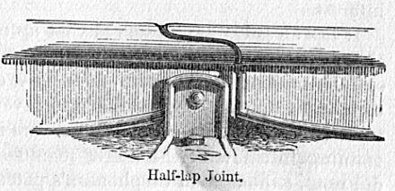
quality of the track by devising a better means of joining the rails together ―
with half-lap rather than butt joints ― and for supporting the joint. Together with the
steam springs referred to, these innovations also became the subject
of a patent:
“A grant unto William Losh, of the town and
county of Newcastle-upon-Tyne, iron founder, and George Stephenson,
of Killingworth, in the county of Northumberland, engineer, for
their invented new method or new methods of facilitating the
conveyance of carriages, and all manner of goods and materials along
railways and tram-ways, by certain inventions and improvements in
the construction of the machine, carriages, carriage wheels,
railways, and tram-ways employed for that purpose.”
Patent Record Office, No
4067, 30th September, 1816.
Stephenson’s activities at this time, together with his views on
steam road vehicles, are dealt with in the 1869 article taken from the
Locomotive Engineers Journal at Appendix III.
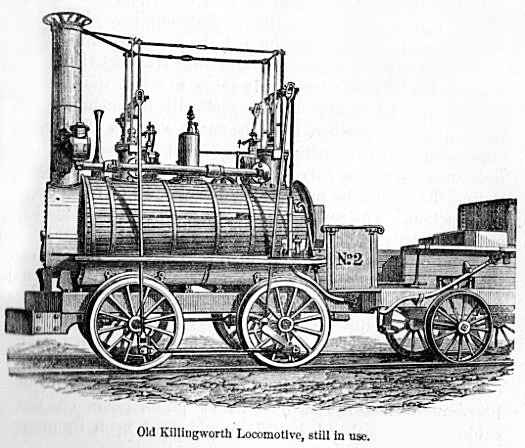
The eventual form of Stephenson’s
Killingwoth locomotives.
In 1820, Stephenson was engaged by the owners of Hetton Colliery to
build an 8-mile railway linking the colliery to coal staithes on the
River Wear near Sunderland. Opened in 1822 (Appendix
IV.), the line
has the distinction of being the first railway (albeit private) designed to be
mechanically operated, in this case by a combination of locomotives
and stationary engines:
“On the original Hetton line there were five self-acting
inclines—the full wagons drawing the empty ones up—and two inclines
worked by fixed reciprocating engines of sixty-horse power each. The
locomotive travelling engine, or ‘the iron horse,’ as the people of
the neighbourhood then styled it, worked the rest of the line. On
the day of the opening of the Hetton Railway, the 18th of November,
1822, crowds of spectators assembled from all parts to witness the
first operations of this ingenious and powerful machinery, which was
entirely successful. On that day five of Stephenson’s locomotives
were at work upon the railway, under the direction of his brother
Robert; and the first shipment of coal was then made by the Hetton
Company at their new staiths on the Wear. The speed at which the
locomotives travelled was about four miles an hour, and each engine
dragged after it a train of seventeen wagons weighing about
sixty-four tons.”
The Life of George Stephenson,
Railway Engineer, Samuel Smiles (1858).
The five locomotives referred to ― built by Stephenson between 1820
and 1822 ― were developments of the 0-4-0 engines use at
Killingworth, with two in-inline vertical cylinders, chain-coupled
wheels and steam suspension.
――――♦――――
THE STOCKTON
AND DARLINGTON RAILWAY
An important development to emerge from the project to build the Stockton and Darlington
Railway (Appendix V.), was the creation, in 1823, of Robert Stephenson and
Company, the world’s first company specifically set up to build
railway locomotives. Until then, locomotives had been
manufactured locally, either in colliery workshops or general
engineering firms, [19] but Stephenson:
“. . . . had long felt that the accuracy and style of their
workmanship admitted of great improvement, and that upon this the
more perfect action of the locomotive engine, and its general
adoption, in a great measure depended. One principal object that he
had in view in establishing the proposed factory was to concentrate
a number of good workmen for the purpose of carrying out the
improvements in detail which he was from time to time making in his
engine; for he felt hampered by the want of efficient help from
skilled mechanics, who could work out in a practical form the ideas
of which his busy mind was always so prolific.”
The Life of George Stephenson,
Railway Engineer, Samuel Smiles (1858).
The company was set up by George Stephenson and his son Robert, Edward
Pease, Michael Longridge (a partner in the Bedlington Ironworks)
and Thomas Richardson, an iron founder and Pease’s cousin. Their
workshop was in premises at Forth Street, Newcastle, where the first works
manager was Timothy Hackworth, who soon moved to take up an
appointment with the Stockton and Darlington Railway,
there to become a distinguished mechanical engineer.
Timothy Hackworth probably had a hand in the design of the first
locomotive to leave the Forth Street works, which was of the usual
0-4-0 type, much in the Killingworth/Hetton tradition. Named Active,
by the opening of the Stockton and Darlington Railway, at which
event she hauled the inaugural train, she bore the name
Locomotion No. 1.
Locomotion No. 1,
Stockton and Darlington Railway (1825).
Steam, produced in a centre flue boiler, drove two in-line
vertical cylinders enclosed within the boiler, before being
exhausted into the chimney. Piston rods were coupled by crossheads
to the connecting rods, a major departure being that coupling rods
now replaced the endless chain; these
required return-cranks to be fitted to the wheels on the rear axle in
order to clear the connecting rod. A single crank set on the front
axle operated the valves for both cylinders, but because this gave an
angular advance in each running direction, valves with a form of lap and lead
were fitted. Stephenson’s
steam suspension had by now been abandoned.
Replica of Locomotion No. 1
pictured during the 1925 centenary cavalcade.
Locomotion No. 1 was followed by three further locomotives of the
class, Hope (November 1825), Black Diamond (April 1826) and
Diligence (May 1826). Each exhibited a major weakness inherent their
single flue boilers, an abysmally poor thermal
efficiency. While heavy fuel consumption presented no significant
drawback in areas where fuel was cheap and plentiful, elsewhere the
steam locomotive would have proved more expensive to operate than
horse traction. Referring to the Locomotion class, the author of the
following article gives some idea of the extent of the heat wasted
in a single flue boiler (exacerbated by wasteful combustion due to the absence of an
external firebox):
“These were constructed after Stephenson’s most matured designs, and
embodied all the improvements which he had contrived up to that
time. No. 1 engine, the ‘Locomotion,’ which was first delivered,
weighed about eight tons. It had one large flue or tube through the
boiler, by which the heated air passed direct from the furnace at
one end, lined with fire bricks, to the chimney at the other. The
combustion in the furnace was quickened by the adoption of the
steam-blast in the chimney. The heat raised was sometimes so great,
and it was so imperfectly abstracted by the surrounding water, that
the chimney became almost red hot.”
Locomotive Engineers’ Journal, Vol. 4, January 1870.
The situation was improved by converting the boilers in these
locomotives to return flue, as in Trevithick’s Catch-Me-Who-Can,
which increased the heating area from 63 to 125 square feet. This
doubled the boiler’s evaporative power, but at the inconvenience of placing
the fireman at the opposite (chimney) end of the boiler to the
driver.
Comparing Stephenson’s Locomotion No. 1 with Trevithick’s
Catch-Me-Who-Can, of 1808, it is difficult to see that any material
advance had been made in locomotive and boiler design during the
intervening years. Locomotion’s coupled driving wheels were,
perhaps, the only significant distinguishing feature, although
Rocket, of 1829, while greatly advanced in other ways, reverted to
the twin driving wheels last employed by Trevithick. Thus, while
Stephenson undoubtedly promoted the steam railway locomotive as the
universal workhorse it was to become, several fundamental
improvements were yet to be made:
“. . . . Stephenson foresaw the further advantage of locomotive
power, and he had an abiding faith in the Locomotive Engine. As
improvements appeared he distinguished them clearly, and applied
them successfully, in most instances at least; for in the
Killingworth, Hetton, and Stockton and Darlington engines he
overlooked the advantages of the return flue boiler and small
chimney of the Wylam engine. But there is no ground for asserting,
as has been done, that George Stephenson was the inventor of any
essential part of the Locomotive Engine; and it is difficult to say
in what respect he improved its structure or working, otherwise than
by adopting and successfully executing the plans and suggestions of
plans of others. There was, indeed, great merit in this, ― as much
probably as Stephenson ever claimed for himself in this respect; and
it no more detracts from his acknowledged sagacity and skill as an
engineer, or his singular worth as a man, that he did not ‘invent’
the Locomotive Engine, than it is a reproach to Sir Isaac Newton
that he did not originate the electric telegraph.”
Locomotive Engineering, and the
Mechanism of Railways, Colburn and Clark (1871).
By comparison, Trevithick had the greater imagination ― perhaps even
a touch of genius about him ― but, sadly, his inability to persevere
was his undoing:
“Trevithick began better than Stephenson: he had friends in Cornwall
and in London; and he ought not to have left to Stephenson to work
out the locomotive engine and the railway. Trevithick was always
unhappy and always unlucky; always beginning something new, and
never ending what he had in hand. The world ever went wrong with
him, as he said, ― but in truth he always went wrong with the world. The world had done enough for him, had he known or had he chosen to
make a right use of any one thing. He found a partner for his
high-pressure engine, ― he built a locomotive, ― he had orders for
others for Merthyr Tydvil and for Wylam, ― he set his ballast engine
to work, ― and he drove his tunnel under the Thames for a thousand
feet; ― but no one thing did well; all were afraid, and at length no
one would have anything to do with him. It was not that his mind was
more fruitful than that of Stephenson, who in this short time had
made improvements in pit work, and railways, built a locomotive, and
found out the safety lamp, and who throughout his life was ever
working out something new. What it was, was this ― Stephenson never
lost a friend, and Trevithick never kept one.”
Civil Engineer and Architect’s
Journal, p.300, Vol. XI. 1848.
CHAPTER
3
――――♦――――
APPENDIX I.
BLENKINSOP’S LOCOMOTIVE
From the Leeds Mercury, 18th July, 1812.
In our paper of the 27th ult. we mentioned a successful experiment
made on the Iron-rail-way between Hunslet and Leeds, to ascertain
the powers of a Steam-impelled Machine, by which the conveyance of
coals, minerals, and other articles is facilitated, and the use of
horses dispensed with. This Machine, at once so simple, powerful and
beneficial, has, as was to be expected, excited a considerable share
of public attention, and we now subjoin a Drawing of the Machine and
toothed Rail-way, accompanied by an abstract of the Specification of
the Patent granted on the 10th of April, 1811, to the Inventor, Mr.
JOHN BLENKINSOP, of
Middleton, near this place.
SPECIFICATION.
—First, There is placed upon the road over which the
conveyance is to he made, a toothed Rack or longitudinal piece of
cast-iron, having the teeth or protuberances standing either
upwards, or downwards, or sideways, in any required position; and
this toothed Rack is continued and duly placed all along, or as far
as may be required upon the ground or road.
— Secondly, There is connected with a Carriage required to bear and
convey goods alone the road, a Wheel having teeth at the
circumference thereof, so formed and placed as to become connected
with, and fairly to act upon the teeth belonging to the rack when
the Carriage shall he suitably placed with regard to the same.
— Thirdly, The Wheel is made to revolve and drive the Carriage along
by the application of a Steam- Engine placed upon and carried along
with the Carriage. And further, the Wheel is connected with the
first mover by a Crank, assisted by a Fly, and the connection is
made either directly with the arbor of the wheel, or indirectly by
other wheel-work, when the crank or other driving piece cannot with
convenience or effect be fixed upon the arbor of the wheel.
— Fourthly, In order to render the motion of the carriage more easy,
the Patentee avails himself of the contrivances and expedients
heretofore used for improving roads, such as Platforms, Pavements,
connected Timbers, and more especially the Iron rail-way, upon which
the untoothed or common wheels of the carriage are made to run, and
in that case the longitudinal pieces are connected with the
Rail-road itself, or otherwise by preference. One of the sides or
range of pieces forming the said Rail-way is cast with teeth, that
the same side or range shall constitute the toothed Rack, and at the
same time afford a regular and even bearing for the Wheels and for
the Toothed wheel, which (if its plane be vertical,) may he made
with a side run to bear upon the smooth part of the Rail and prevent
the teeth from locking too deep.
― And lastly, Motion is given to other carriages by attaching the
same to the carriage upon which the first mover is placed and these
other carriages are fitted up as usual without the Toothed-wheel,
and where the same may be preferred, use is made of two
Toothed-wheels, acting upon correspondent racks on each side.
――――♦――――
APPENDIX II.
THE DODDS AND STEPHENSON PATENT
From:
Patents for Inventions.
Abridgements of Specifications Relating to the Steam Engine,
Vol. I (1871).
A.D. 1815, February 28. ― No. 3887.
DODDS, Ralph, and STEPHENSON, George. “The friction of four wheels
propelled by two engines will propel several tons weight upon an
iron railway. This was done by a cog-wheel upon each bearing axis,
spurred on by a cog-wheel upon each engine’s axis, with an interleading cog wheel to combine the two engines together and keep
them at right angles from one another.” Another method was “to
combine the two engines together with cog-wheels which spur
themselves along a cog railway or waggon way;” “but we,” say the
Patentees, “apply the power of the engine to the travelling wheels
of the carriage, by joining one end of each connecting rod to a pin
fixed to one of the spokes of each of the travelling wheels; which
connecting rods are joined at both ends by ball and socket joints,
to give way to the rise and fall of the road; and there is also a
joint where the piston rod is joined to the yoke, that it may give
way to the ball and socket joints.” “The engines are kept at their
proper distance apart by each bearing axle having two cranks near
its centre with two connecting rods fitted at right angles to each
other, and extending from one crank to the other.”
2. Or two grooved wheels that have notches into which the projecting
bolts of the endless chain fall, and in which it works, are fixed in
the centre of each axle.
3. Applying the friction of the bearing wheels in this way, the
engines propel 60 tons or upwards upon an iron railway. If a greater
burden is to be moved, the friction of other two wheels is added,
and they are made to carry the water that supplies the engine. A
groove is made in each, and a groove in the last two bearing wheels
of the carriage, into which an endless chain falls. By the
propelling force of the engine this is moved along, together with
the bearing wheels of the water carriage attached to it.
――――♦――――
APPENDIX III.
GEORGE STEPHENSON’S
EARLY RAILWAY DEVELOPMENTS
from the
Locomotive Engineers Journal,
Volume 3 (1869).
Mr. Stephenson’s experiments on fire damp and his labours in
connection with the invention of the safety lamp, occupied but a
small portion of his time, which was mainly devoted to the
engineering business the colliery. He was also giving daily
attention to the improvements of his locomotive, which every day’s
observation and experience satisfied him was still far from being
perfect.
At that time, railways were almost exclusively confined to the
colliery districts, and attracted the notice of few persons except
those immediately connected with the coal trade. Nor were the
colliery proprietors generally favourable to locomotive traction. There were great doubts as to its economy. Mr. Blackett’s engines at
Wylam were still supposed to be working at a loss; the locomotives
tried at Coxlodge and Heaton, proving failures, had been abandoned;
and the colliery owners seeing the various locomotive speculations
prove abortive, ceased to encourage further experiments Stephenson
alone remained in the field after all the other improvers and
inventors of the locomotive had abandoned it in despair. He
continued to entertain confident expectations of its eventual
success. He even went so far as to say that it would yet supersede
every other tractive power. Many looked upon him as an enthusiast,
which no doubt he was, but upon sufficient grounds. As for his
travelling engine, it was by most persons regarded as a curious toy;
and many, shaking their heads, predicted for it “a terrible blow up
some day.” Nevertheless, it was daily performing its work with
regularity, dragging the coal wagons between the colliery and staiths, and saving the labour of many men and horses. There was
not, however, so marked a saving in the expense of working, when
compared with the cost of horse traction, as to induce the northern
colliery masters to adopt it as a substitute for horses. How it
could be improved and rendered more efficient as well as economical
was never out of Mr. Stephenson’s mind. He was quite conscious of
the imperfections both of the road and of the engine; and he gave
himself no rest until he had brought the efficiency of both up to a
higher point. He worked his way step by step, slowly but surely;
every step was in advance of the one preceding, and thus inch by
inch was gained and made good as a basis for further improvements.
At an early period of his labours, or about the time when he had
completed his second locomotive, he began to direct his particular
attention to the state of the road; as he perceived that the
extended use of the locomotive must necessarily depend in a great
measure upon the perfection, solidity, continuity, and smoothness of
the way along which the engine travelled. Even at that early period,
he was in the habit of regarding the road of the locomotive as one
machine, speaking of the rail and the wheel as “man and wife.”
All railways were at that time laid in a careless and loose manner,
and great inequalities of level were allowed to occur without much
attention being paid to repairs; the result was that great loss of
power caused, and also great wear and tear of machinery, by the
frequent jolts and blows of the wheels against the rails. His first
object, therefore, was to remove the inequalities produced by the
imperfect junction between rail and rail. At that time (1816) the
rails were made of cast-iron, each rail being about three feet long;
and sufficient care was not taken to maintain the points of junction
on the same level. The chairs, or cast-iron pedestals into which the
rails were inserted, were flat at the bottom; so that whenever any
disturbance took place in the stone blocks or sleepers supporting
them, the flat base of the chair upon which the rails rested, being
tilted by unequal subsidence, the end of one rail became depressed,
whilst that of the other was elevated. Hence constant jolts and
shocks, the reaction of which very often caused the fracture of the
rails, and occasionally threw the engine off the track.
To remedy this imperfection, Mr. Stephenson devised a new chair,
with an entirely new mode of fixing the rails therein. Instead of
adopting the butt joint, which had hitherto been used in all
cast-iron rails, he adopted the half-lap joint by which means the rails
extended a certain distance over each other at the ends, somewhat
like a scarf joint. These ends, instead of resting upon the flat
chair, were made to rest upon the apex of a curve forming the bottom
of the chair. The supports were extended from three feet nine inches
or four feet apart. These rails were accordingly substituted for the
old cast-iron plates on the Killingworth Colliery Railway, and they
were found to be a very great improvement upon the previous system,
adding both to the efficiency of the horse power (still used on the
railway) and to the smooth action of the locomotive engine, but more
particularly increasing the efficiency the latter.
This improved form of the rail and the chair was embodied in a
patent taken out in the joint names of Mr. Losh, of Newcastle,
iron-founder, and of Mr. Stephenson, bearing date the 30th of
September, 1816. [A grant unto William Losh, of the town and county
of Newcastle-upon-Tyne, iron founder, and George Stephenson, of
Killingworth, in the county of Northumberland, engineer, for their
invented new method or new methods of facilitating the conveyance of
carriages, and all manner of goods and materials along railways and
tram-ways, by certain inventions and improvements in the
construction of the machine, carriages, carriage wheels, railways,
and tram-ways employed for that purpose ― 30th September, 1816,
Patent Record Office, No. 4067.]
Mr. Losh being a wealthy, enterprising iron manufacturer, and having
confidence in George Stephenson and his improvements, found the
money for the purpose of taking out the patent, which in those days
was a very costly as well as troublesome affair.
The specification of the same patent also described various
important improvements on all locomotives previously constructed. The wheels of the engine were improved, being altered from cast to
malleable iron, in whole or in part, by which they were made lighter
as well as more durable and safe. Thus the road was rendered
smoother, and the wheels of the locomotive were made stronger. But
the most ingenious and original contrivance embodied in this patent
was the substitute for springs, which was deviated by Mr.
Stephenson. He contrived an arrangement by which the steam generated
in the boiler was made to perform this important office! The means
by which this was effected were so strikingly characteristic of true
mechanical genius, that we would particularly call the reader’s
attention to this ingenious device, which was the more remarkable,
as it was contrived long before the possibility of steam locomotion
had become an object of parliamentary inquiry, or even of public
interest.
It has already been observed that up to, and indeed for some time
after, the period of which we speak, there was no such class of
skilled mechanics, nor were there any such machinery and tools in
use as are now at the disposal of inventors and manufacturers. The
same difficulty had been experienced by Watt many years before, in
the course of his improvements in the steam-engine; and on the
occasion of the construction of his first condensing engine at Soho,
Mr. Smeaton, although satisfied of its great superiority over Newcomen’s, expressed strong doubts as to the practicability of
getting the different parts executed with the requisite precision;
and he consequently argued that, in its improved form, this powerful
machine would never be generally introduced. Such was the low state
the mechanical arts in those days. Although skilled workmen were in
course of gradual training in a few of the larger manufacturing
towns, they did not, at the date of Stephenson’s patent, exist in
any considerable numbers, nor was there then any class of mechanics
capable constructing springs of sufficient strength and elasticity
to support a locomotive engine ten tons in weight.
The rails then used being extremely light, the road soon became worn
down by the traffic, and, from the inequalities of way, the whole
weight of the engine, instead of being uniformly distributed over
the four wheels, was occasionally thrown almost diagonally upon two. Hence frequent jerks of the locomotive, and increased strength upon
the slender road, which occasioned numerous breakages of the rails
and chairs, and consequent interruptions to the safe working of the
railway.
In order to avoid the dangers arising from this cause, Mr.
Stephenson contrived his steam springs. He so arranged the boiler of
his new patent locomotive that it was supported upon the frame of
the engine by four cylinders, which opened into the interior of the
boiler. These cylinders were occupied by pistons with rods, which
passed downwards and pressed upon the upper side of the axles. The
cylinders opening into the interior of the boiler, allowed the
pressure of steam to be applied to the upper side of the piston; and
that pressure being nearly equivalent to one forth of the weight of
the engine, each axle, whatever might be its position, had at all
times nearly the same amount of weight to bear, and consequently the
entire weight was at all times pretty equally distributed amongst
the four wheels of the locomotive. Thus the four floating pistons
were ingeniously made to serve the purpose of springs in equalizing
the weight, and in softening the jerks of the machine; the weight of
which, it must also be observed, had been increased, on a road
originally calculated to bear a considerably lighter description of
carriage. This mode of supporting the engine remained in use until
the progress of spring making had so far advanced that steel springs
could be manufactured of sufficient strength to be used in
locomotives.
The result of the actual working of George Stephenson’s new
locomotive and improved road amply justified the promises held forth
in his “specification.” The traffic was conducted with greater
regularity and economy, and the superiority of the locomotive
engine, as compared with horse traction, became more apparent. And
it is a fact worthy of notice, the identical engines constructed by
Mr. Stephenson in 1816, are to this day to be seen in regular useful
work upon the Killingworth railway, conveying heavy coal trains at
the speed of between five and six miles an hour, probably as
economically as any of the more perfect locomotives now in use.
Mr. Stephenson’s endeavours having been attended with such marked
success in the adaptation of locomotive power to railways, his
attention was called by many of his friends, about the year 1818, to
the application of steam to travelling on common roads. It was from
this point, indeed, that the locomotive had been started.
Trevithick’s first engine having been constructed with this special
object. Stephenson’s friends having observed how far behind he had
left the original projector of the locomotive in its application to
railroads, perhaps naturally inferred that he would be equally
successful in applying it to the purpose for which Trevithick and
Vivian originally intended it.
But the accuracy with which estimated the resistance to which loads
were exposed on railways, arising from friction and gravity, led him
at a very early stage to the idea of ever successfully team power to
common road travelling. In October, 1818, he made a series of
careful experiments, in conjunction with Mr. Nicholas Wood, on the
resistance to which carriages were exposed on railways, testing the
results by means of a dynamometer of his own construction. His
readiness at all times with a contrivance to enable him to overcome
a difficulty, and his fertility in expedients, were in no respect
more strikingly displayed than in the invention of this dynamometer. Though it was found efficient for the purpose for which it was
contrived, it will not, of course, bear a comparison with other
instruments for a similar purpose that have since been invented. The
series of practical observations made by means of this instrument
were interesting, as the first systematic attempt to determine the
precise amount of resistance to carriages moving along railways.
[The experiments are set forth in detail in “A Practical Treatise
on Railroads and Interior Communications in General.” By
Nicholas Wood, Colliery Viewer, C.E., London: Hurst, Chance & Co.,
ed. 1831, pp. 197-253.]
It was thus for the first time ascertained by experiment that the
friction was a constant quantity at all velocities. Although this
theory had long before been developed by Vince and Coulomb, and was
well known to scientific men as an established truth, yet at the
time when Mr. Stephenson made his experiments, the deductions of
philosophers on the subject were neither believed in nor acted upon
by practical engineers. And notwithstanding that the carefully
conducted experiment in question went directly to corroborate the
philosophical theories on the subject, it was a considerable time
(so great were the prejudices then existing) before the conclusions
which they established received the sanction of practical men.
It was maintained by many that the results of these experiments led
to the greatest possible mechanical absurdities. For example, it was
insisted that, if friction was constant at all velocities upon a
level railway, when once a power was applied to a carriage, which
exceeded the friction of that carriage by the smallest possible
amount, such excess of power, however small, would be able to convey
the carriage along a level railway at all conceivable velocities.
When this position was taken by those who opposed the conclusions to
which Mr. Stephenson had arrived, he felt the greatest hesitation in
maintaining his own views; for it appeared to him at first sight
really the absurdity which his opponents asserted it to be. Frequent
and careful repetition of his experiments, however, left no doubt
upon his mind as to the soundness of his conclusions ― that friction
was uniform at all velocities. Notwithstanding the ridicule that was
thrown upon his views by many persons with whom he associated at the
time, he continued to hold to this conclusion as a fact positively
established; and he soon afterwards boldly maintained, that that
which was an apparent absurdity was indeed an inevitable
consequence, and that every increase of speed involved a necessary
expenditure of power almost in a direct ratio.
It is unnecessary at this time of day to point out how obvious this
consequence is, and how it is limited and controlled by various
circumstances; never-the-less it is doubted, that could you always
be applying a power proportionately in excess of the resistance, a
constant increase of velocity would follow without any limit. This
is so obvious to professional men now, and is indeed so axiomatic,
that it is unnecessary further to illustrate the position; and the
discussions which took place on the subject, when the results of Mr.
Stephenson’s experiments were announced, are only here alluded to
for the purpose of showing the difficulties he had to contend with
and overcome at the time, and how small was the amount of science
then blended with engineering practice.
(Some years afterwards, Mr. Sylvester, of Liverpool, published an
able pamphlet on this subject, in which he demonstrated in a very
simple and beautiful manner, the correctness of Mr. Stephenson’s
conclusions.)
The other resistances to which carriages are exposed, were at the
same time investigated by Mr. Stephenson. He perceived that these
resistances were mainly three: the first being upon the axles of the
carriage, the second (which may be called the rolling resistance)
being between the circumference of the wheel and the surface of the
rail, and the third being the resistance of gravity. The amount of
friction and gravity was accurately ascertained; but the rolling
resistance was a matter of greater difficulty, being subject to
great variation. He however satisfied himself that it was so great
when the surface presented to the wheel was of a rough character,
that the idea of working steam carriages common roads was dismissed
him as entirely out of the question. Even so early as the period to
(1818) he brought his calculations to a practical test: he scattered
sand upon the rails an engine was running, and that a small quantity
was quite sufficient to retard and even to stop the most powerful
locomotive that had at that time made. And he never failed to urge
this conclusive experiment upon the attention those who were at that
time their money and ingenuity upon vain attempt to apply steam to
the purpose of travelling on common roads.
Having ascertained that resistance might be taken as represented by
10 lbs to a ton weight on a level railway, it became obvious to him
that so small a rise as 1 in 100 would diminish the useful effort of
a locomotive by upwards of 50 per cent. This was demonstrated by
repeated experiments, and the important fact thus rooted deeply in
his mind, was never lost sight of in the course his future railway
career. It was owing in a great measure to these painstaking
experiments that he thus early became convinced of the vital
importance, in an economical point of view, of reducing the country
through which a railway was to pass as nearly as possible to a
level. Where, as in the first coal railways of Northumberland and
Durham, the load was nearly all one way ― that is from the colliery
to the shipping place -- it was an advantage to have an inclination
in that direction. The strain on the powers of the locomotive was
thus diminished, and it was an easy matter for it to haul the empty
wagons back to the colliery up even a pretty steep incline. But when
the loads were both ways, it appeared obvious to him that the
railroad must be constructed as nearly as possible on a level. The
strong and sagacious mind of Stephenson early recognized this broad
principle; and he had so carefully worked out the important facts as
to the resistance offered by adverse gradients, that he never
swerved from it. At a much later period, when the days of fast
engineering had arrived, while many thought him prejudiced on this
point, he himself clung tenaciously to it, and invariably insisted
upon the importance of flat gradients. It is true, great and
important additions were made to the powers of the locomotive, but
no sooner were these effected, than lines of steeper and still
steeper gradients were devised, until, as he used to declare,
engineers were constantly neutralizing the increased powers of the
engine, and in precisely the same degree diminishing the comparative
advantages of over common roads.
These views, thus early entertained, originated in Mr. Stephenson’s
the peculiar character of railroad works as distinguished from all
roads; for, in railroads, he contended that large sums be wisely
expended in perforating barriers of hills with tunnels, and in
raising the levels with the excess cut down from the adjacent high
ground. In proportion as these views forced themselves upon his
mind, and were corroborated by his daily experience, he became more
and more convinced of the hopelessness of applying steam locomotion
to common roads; for every argument in favour of a level railway
was, in his view, an argument against the rough and hilly course of
a common road. Nor did he cease to urge upon the numerous patrons of
road steam carriages, that if, by any amount of ingenuity, an engine
could be made, which could by possibility travel on a turnpike road
at a speed equal to that obtainable by horse power, and at less
cost, such an engine if applied to the more perfect surface of a
railway would have its efficiency enormously enhanced.
For instance, he calculated that, if an engine had been constructed,
and had been found to travel uniformly between London and Birmingham
at an average speed of 10 miles an hour, conveying say 20 or 30
passengers, at a cost of 1s. per mile, it was clear that the same
engine, if applied to a railway, instead of conveying 20 or 30
persons, would easily convey 200 or 300; and, instead of travelling
at a speed of 10 or 12 miles an hour, a speed at least 30 or 40
miles an hour might be attained.
All this seems trite and commonplace enough, now that the thing has
been done; but it was not so in those days, before it had been
attempted or even thought of, excepting by one man, whom his
cotemporaries spoke of as a dreamer and enthusiast on the subject of
railways. Then, the so called “practical” men were bent upon a
really impracticable thing ― the economical application of steam
power to turnpike roads; while the “enthusiast” was pursuing the
only safe road to practical success. At this day it is difficult to
understand how the sagacious and strong common-sense views of
Stephenson on this subject, failed to force themselves sooner upon
the minds of those who were persisting in their vain though
ingenious attempts to apply locomotive power to ordinary roads. For
a long time they continued to hold with obstinate perseverance to
the belief that, for steam purposes, a soft road was better than a
hard one ― a road easily crushed better than one incapable of being
crushed: and they held to this after it had been demonstrated in all
parts of the mining districts, that iron tram-ways were better than
paved roads. But the fallacy that iron was incapable of adhesion
upon iron, continued to prevail, and the projectors of steam
travelling on common roads only shared in the common belief. They
still considered that roughness of surface was essential to produce
“bite,” especially in surmounting acclivities; the truth being that
they confounded roughness of surface with tenacity of surface and
contact of parts; not perceiving that a yielding surface which would
adapt itself to the tread of the wheel, could never become an
unyielding surface to form a fulcrum for its progression. It was the
error of reasoning from one circumstance, instead of taking all the
circumstances into account.
――――♦――――
APPENDIX IV.
THE OPENING OF THE HETTON RAILWAY.
From the Morning Chronicle, 28th November, 1822.
HETTON COLLIERY, DURHAM. ― On Monday, the 18th inst. the Hetton Coal
Company effected the first shipment of their coals at their newly
erected staith on the banks of the river Wear, at Sunderland. The waggon-way, which extends over a space of eight miles, from the
colliery to the river, and in its course crosses Warden Law (one of
the highest hills in this part of the country), was crowded with
spectators to witness the first operations of the powerful and
ingenious machinery employed for conveying the coal-waggons. Five of
Mr. George Stephenson’s patent travelling engines, two 60-horse
power fixed reciprocating engines, and five self-acting inclined
planes (all under the direction of Mr. Robert Stephenson, the
company’s resident engineer), simultaneously performing their
various and complicated offices with the precision and exactness of
the most simple machinery, exhibited a spectacle at once interesting
to science, and encouraging to commerce.
The good quality of the coals is universally acknowledged; and the
shipment of them has been anxiously looked for by the ship owners
and fitters at Sunderland, who had the gratification of witnessing
about 100 waggon loads (containing upwards of 100 tons weight)
conveyed along the iron-railway (which was furnished my Messrs. Losh,
and Co.) with astonishing facility and dispatch, to the company’s staith, where the coals were shipped by their newly-invented
self-discharging apparatus.
The crowds of people assembled on the occasion, the flags and
colours streaming from every building, with the cheerful airs of the
Newbottle band, rendered the scene most lively and exhilarating. Extensive commercial speculations are as grateful to philanthropy as
they are animating to science. Whilst they call forth the powers of
genius, they, at the same time, afford subsistence and comfort to
the labouring classes of society; and, we trust, there are none who
will withhold the meed of praise from undertakings like the present,
which has for two years given constant employment to many hundreds
of individuals and their families, and opened a cheering prospect to
the working part of the community in the coal districts.
After the business of the day, the owners of the colliery, with
about fifty of their friends, who had been invited to celebrate the
event, sat down to an excellent dinner, at Miss Jowsey’s, the Bridge
Inn, Bishopwearmouth.
――――♦――――
APPENDIX V.
THE OPENING OF STOCKTON
AND DARLINGTON RAILWAY.
From the Manchester Courier, 8th October, 1825.
On Tuesday last, that great work, the Darlington and Stockton
railway was formally opened by the proprietors, for the use of the
public. It is a single of railway twenty-five miles in length, and
will open the London market to the collieries in the western part of
the county of Durham, as well as facilitate the obtaining of fuel to
the country along its line, and the northern parts of Yorkshire.
The line of railway extends from the collieries in a direction
nearly from west to east from Witton Park and Etherly, near West
Auckland, to Stockton-upon-Tees, with branches to Darlington, Yarm,
&c., and is chiefly composed of malleable iron rails. At the western
extremity of the line a deep ravine occurs at the river Gaundless,
on the summit of the hills, in each side of which, permanent
steam-engines are fixed for the purpose of conveying the goods
across the two ridges. The engine on the western side of the vale is
called the Etherly engine, and that on the eastern side the
Brusselton engine; the latter of which, in addition to conveying the
goods up from West Auckland, also continues the transit down the
eastern side of the ridge: below this to the east, the country,
though undulating, is pretty flat, and the conveyance is performed
by locomotive engines.
To give éclat to the public opening of the road, a programme was
issued, stating that the proprietors would assemble at the permanent
steam-engine, below Brussleton Tower, about nine miles west of
Darlington, at eight o‘clock. Accordingly, the committee, after
inspecting the Etherly engine plane, assembled at the bottom of
Brusselton engine plane, near West Auckland, and here the carriages,
loaded with coals and merchandise, were drawn up the eastern ridge
by the Brussleton engine, a distance of 1960 yards, in seven minutes
and a half, and then lowered down the plane on the east side of the
hill, 880 yards in five minutes. At the foot of the plane, the
locomotive engine was ready to receive the carriages, and here the
novelty of the scene and fineness of the day attracted an immense
concourse of spectators—the fields on each side of the railway being
literally covered with ladies and gentlemen on horseback, and
pedestrians of all kinds.
The train of carriages were then attached to a locomotive engine of
the most improved construction, and built by Mr. George Stephenson,
in the following order: ― 1. Locomotive engine, with the engineer
(Mr. Stephenson) and assistants. ― 2. Tender, with coals and
water―next, six carriages loaded with coals and flour ― then an
elegant covered coach, with the committee and other proprietors of
the railway―then twenty-one waggons, fitted up on the occasion for
passengers ― and, last of all, six waggons loaded with coal, making
altogether a train of thirty-eight carriages, exclusive of the
engine and tender. Tickets were distributed to the number of near
three hundred, for those who it was intended should occupy the coach
and the waggons; but such was the pressure and crowd, that both
loaded a empty carriages were instantly filled with passengers.
The signal being given, the engine started off with this immense
train of carriages, and here the scene became most interesting ― the
horsemen galloping across the fields to accompany the engine, and
the people on foot running on each side of the road, endeavouring in
vain to keep up with the cavalcade. The railway descending with a
gentle inclination towards Darlington, though not uniform, and the
rate of speed was consequently variable. On this part of the railway
it was intended to ascertain at what rate of speed the engine could
travel with safety. In some parts the speed was frequently twelve
miles per hour; and in one place, for a short distance, near
Darlington, fifteen miles per hour; and, at that time, the number of
passengers were counted to four hundred and fifty, which, together
with the coals, merchandize, and carriages, would amount to near
ninety tons.
After some little delay in arranging the procession, the engine,
with her load, arrived at Darlington, a distance of eight miles and
three quarters, in sixty-five minutes, exclusive of stops, averaging
about eight miles an hour. Six carriages, loaded with coals,
intended for Darlington, were then left behind; and, after obtaining
a fresh supply of water, and arranging the procession to accommodate
a band of music and passengers from Darlington, the engine set off
again. Part of the railway from Darlington to Stockton has little
declivity, and in one place is quite level; and, as in the upper
part it was intended to try the speed of the engine; in this part it
was intended to prove her capability of dragging a heavy load, and
certainly the performance excited the astonishment of all present,
and exceeded the most sanguine expectations of every one conversant
with the subject.
The engine arrived at Stockton in three hours and seven minutes
after leaving Darlington, including stops, the distance being nearly
twelve miles, which is at the rate of four miles an hour; and upon
the level part of the railway, the number of passengers in the
waggons were counted about five hundred and fifty, and several more
clung to the carriages on each side, so that the whole number could
not he less than six hundred, which, with the other load, would
amount to about eighty tons.
A number of gentlemen from Liverpool and Birmingham were present at
the opening. |
.htm_cmp_poetic110_bnr.gif)