|
NOTES AND EXTRACTS
ON THE HISTORY OF THE
LONDON & BIRMINGHAM RAILWAY
CHAPTER 3.
PROBLEMS WITH THE TRACK
THE CAST-IRON PLATE RAIL
The development of the railway locomotive languished for some years
following Trevithick’s withdrawal from the field. This was not
wholly due to the absence of his inventive genius, nor to the
lack of a commercial driver for change, for the inflationary
pressures of the Napoleonic War had greatly increased the cost of
horse fodder and with it that of horse-powered traction. The
principal reason, as Trevithick had discovered at Pen-y-Darren and
later in London, was the absence of rails capable of withstanding a
locomotive’s weight and hammer blow. [1] More than a
another decade was to pass before rails became available that could
reliably withstand the stresses of locomotive traction.
This chapter reviews the main changes that took place in rail design
and technology leading up to the world’s first passenger-carrying,
steam-worked railway, the Stockton and Darlington.

Iron plate rails mounted on stone
blocks ― the Derby Canal Railway.
The development of the wagonway progressed with the coming of the
Industrial Revolution and the widespread use of iron. First,
wooden rails were reinforced with iron plating to reduce wear and to
further reduce friction. It was then a natural progression to the
all-iron L-shaped rail, [2] which was not
attacked by rot and could better withstand the weight of the wagons:
“Notwithstanding the imperfection both of
the railway and the impelling force, as compared with the improved
apparatus of the present day, the advantage was so considerable,
that a single horse could draw three tons of coals from the pit to
the river. There was, however, a drawback on the advantages, from
the expense of repairing the wear and tear of the decayed wood,
which was, indeed, under some circumstances, so great as to render
the use of rail-ways, made of this material, a very doubtful
benefit. At length iron was introduced, and found to succeed
remarkably well. But in the first instance the railways were not
made wholly of iron. Flat bars of this metal were fastened on the
top of the existing wooden rails, and this was considered a great
improvement. A greater still, however, which soon succeeded, was
making the rails wholly of iron, cast in short bars, united at their
extremities, and resting on square blocks of stone, instead of logs
of wood, arranged at short intervals along each side of the road.”
The British
Magazine, Vol. I., p. 121, 1830.
However, the introduction of iron reinforcement on wood, followed by
the replacement of wood with iron plates, increased wear on the
wagons’ wooden wheels. To combat this, iron tyres were
introduced followed by
iron wheels, both of which also reduced still further a railway wagon’s rolling resistance:
“The next improvement in order of time
appears to have been the use of cast-iron as a substitute for the
wooden rails, and these were tried on a small scale at the Colebrookdale iron works in Shropshire about 1767, at the suggestion
of Mr. Reynolds, one of the partners in that concern. About this
same time cast-iron wheels, turned in a lathe, and made with great
truth and accuracy, began to be used, and then it was that the great
advantage of these roads became apparent, for the advantage to be
gained by a rail-road depends in a great measure on the perfection
of the workmanship bestowed upon it, to make it truly smooth and
level, and on making the carriages that run upon it as free from
friction and inequalities of motion as possible.”
Elements of
Civil Engineering, John Millington (1839).
However, it is doubtful that iron wagon wheels were first used at Colebrookdale. Like much of our railway history, their first use was
probably in the North East of England. [3]
Although there were variations in design, by the end of the 18th
Century a typical iron wagonway consisted of L-shaped plate rails,
which we would describe today as ‘angle irons’. A wagon’s flat-rimmed
wheels ran along the rail’s flat surface (about 3½ inches wide), while
the uprights (about 4 inches high) kept the wheels aligned with the track. This contrasts with a modern railway, where the opposite applies ―
flanges guide the wheel along a flangeless track.
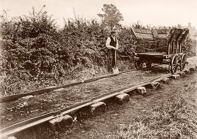
Plateway mounted on stone blocks ―
the Derby Canal Railway.
Plate rails were of cast-iron, generally in lengths of three to six feet, drilled to receive spikes [4]
and supported on either transverse timber sleepers, or on stone
blocks. It seems at this time that track-beds were unballasted, for
where timber sleepers were in use a civil engineering manual of the period speaks of the need to
support their ends:
“. . . . a transverse timber sleeper may be
let into the ground and a large heavy stone, or mass of rubble-work
in mortar, may be sunk below each of its ends to give it a firmer
bearing and prevent its sinking deeper.”
Elements of
Civil Engineering, John Millington (1839).
Where the lines were laid on timber, they were spiked directly into
the sleepers, whereas when laid on stone, holes had to be drilled
into the blocks, plugged with wood, and the lines spiked into the
plug. An advantage of using stone blocks was that the track-bed
between the lines was left clear for the horses’ hooves, but to
achieve this with timber the sleepers had to be let into the ground
or covered with gravel where they then became more prone to rot.
However, stone blocks had their disadvantages; they were more prone than
wood to vibration, which shook the rails loose, while the wooden
plugs gradually saturated and swelled, splitting the stone. Such was the construction of the Pen-y-Darren Tramroad [5]
on which Trevithick’s locomotive ran in 1804.
Besides colliery owners building wagonways, canal companies also
made considerable use of them during the canal era (little
realising they would evolve to supersede the canals), principally as
feeders in situations where they provided a more economic
alternative to a branch canal, or where the terrain was unsuitable
for a waterway. It was in the construction of such feeders that the
civil engineer Benjamin Outram’s name is now associated.
The Derby Canal Railway.
One example of Outram’s work was the ‘Derby Canal Railway’ (aka the
‘Little Eaton Gangway’), a typical wagonway of the period. Now
abandoned, the Derby
Canal was opened throughout in 1796 to form a link
between the Trent & Mersey and the Erewash canals in Derbyshire. As
a more economic alternative to a branch canal, Outram built a
wagonway to link the Denby collieries with the canal at Little Eaton
wharf. Priestly described this plateway thus:
“From the northern end of the main line
[of the canal] at Eaton, a railway
proceeds by Horsley and Kilboum, to Smithy House, which is nearly
four miles and three quarters in length. From Smithy House there is
a branch one mile and three quarters in length, to the collieries at Henmoor, situated one mile and a half east of the town of Belper;
another one mile and a half in length, by the potteries, to the
extensive coal works near Denby Hall; with a collateral branch out
of the last mentioned branch, three quarters of a mile in length, to
other collieries north of Salterswood.”
Historical
Account of the Navigable Rivers, Canals etc., Joseph Priestley
(1831).
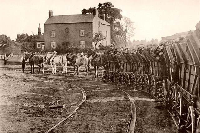
The Derby Canal Railway used cast-iron
L-shaped plate rails, approximately three feet long, which
were spiked into stone sleepers. Its horse-drawn wagons had
detachable bodies, each of a capacity of about 1¾ tons, which were
loaded into barges by crane at Little Eaton Wharf, an early form of
containerisation. The wagonway’s principal cargo was coal, but it also carried stone,
pottery and other goods. It remained in use in its original
horse-drawn form until closure in 1908.
――――♦―――― |
|
THE EDGE RAIL.
William Jessop was one of the great civil engineers of his era, his name
being linked to a wide range of civil engineering projects that
include canals, docks and wagonways. He is also credited with the first use of the cast-iron
edge rail, the
predecessor of the modern railway line. [6]
Around 1794 ― the date is
uncertain ― Jessop engineered a wagonway to carry coal from Nanpantan,
on the Charnwood Forest Canal, to Loughborough. This was to have
been laid with plate rails of the Outram pattern, but, so the story goes, the trustees
of a turnpike road objected to the
obstruction posed by the rails’ raised flanges at a point where the
track crossed the carriageway. However, a further
problem with plate rails was that the debris thrown up
by the horses’ hooves lay on the rail’s flat surface and
obstructed the free running of the wagon wheels. Jessop’s use of
the edge rail solved both problems; where the rails crossed a road,
their upper edges could be recessed so as to lie level with the road
surface, thereby posing no obstruction to
traffic, and elsewhere their raised running surfaces remained substantially free
of stones and dirt.
“Edge rails succeeded plate-rails, having
been first used in 1785; the inconvenience arising from the dust
laying on the latter probably led to their introduction originally,
although the many other advantages possessed by them might hot have
been contemplated at the time, as the form of edge-rails is
certainly very superior, combining the least expenditure of material
with the greatest possible strength and the friction upon them is
less than upon tram-rails.”
A Glossary of Civil Engineering,
S. C. Brees (1844).
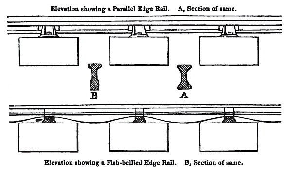
The earliest iron edge rail consisted of a cast-iron bar, laid on
edge and generally
three feet long (due to cast-iron being brittle, it could only be
laid in short lengths). The underside of the rail was
elliptical to provide greater strength between the supports, which
gave rise to the description ‘fish bellied’. The rails were mounted
in a succession of iron chairs, each being spiked to either a timber
or a stone block sleeper. Vehicles that ran upon edge rails
required flanged wheels, which kept them aligned
with the track.
The iron edge rail was not adopted immediately and co-existed with
the plate-rail for some years:
“It was of course a great saving of
material to cast a flange on the tire of the wheels only, instead of
along the whole length of the line; but plate-rails with the flange
upon them continued in use notwithstanding, in virtue of the force
of prejudice. In 1797, Mr. Jessop’s edge-rails were laid down on the
Lawson Main Colliery Railway, near Newcastle; but in 1800, Mr. Wm. Outram laid plate-rails, with a flange, on the Little Eaton Railway,
in Derbyshire. In 1801 the Wandsworth and Croydon Railway was laid
with these flange rails, and in 1803 the Croydon and Merstham
Railway. It was not till about 1812 or 1815 that edge rails got the
mastery.”
The Railway Register, Hyde
Clark (1847).
In 1794, Jessop entered into partnership with Benjamin Outram and
others in an ironworks, ‘Benjamin Outram and Company’, [7]
that Outram had set up some years previously at Butterley in
Derbyshire, and the business began manufacturing both types of rail.
――――♦―――― |
|
LOSH AND STEPHENSON’S PATENT
In 1816, George Stephenson contributed to the development of
the iron edge rail by devising an improved method for joining and
fixing the rails in place. At the time, railways were poorly laid,
the outcome being an uneven track on which locomotives and wagons
were subjected to excessive wear and tear from the considerable
jolts they experienced in passing over protruding rail joints,
sometimes being derailed. Stephenson replaced the existing butt
joints between each rail with half-lap joints, which extended the
rails over each other for a short distance at their ends. He also
redesigned the supporting chair, so that the joint between the rails
rested upon the apex of a curve in place of a flat surface. To
reduce the number of rail joints, the chairs were moved from 3 feet
to 3 feet 9 inches or 4 feet apart.

Fish-bellied rail, showing (top)
curvature in the supporting chair and (bottom) a half-lap joint.
The effect of these changes, while reducing the number of rail
joints, helped to maintain an even line. Were a sleeper to tilt from
the horizontal, the rail would remain tangential to the curved base
of the chair in which it was seated, while the half-lap joint with
the adjacent rail kept it locked in place.
Stephenson, together with William Losh, part owner of Losh, Wilson &
Bell, who at the time employed Stephenson for two days a week at
their Walker Ironworks, applied for a patent to cover this
invention. Registered on 30th September 1816, the patent ― an
extract of which is at Appendix I. ― included
the steam suspension
and the application of malleable iron to rail vehicle wheels
referred to in Chapter 2.
――――♦―――― |
|
THE MALLEABLE IRON RAIL
An important step in the development of the iron rail took place at
the Tindale Fell Railway (aka Lord Carlisle’s Railway), an early
mineral line that served the extensive collieries and lime works at
Tindale Fell in Cumbria. The line had been laid partly with
cast-iron and partly with malleable iron [8]
rails. Over a period of years its operators noticed that while
the malleable iron rails remained in good condition, those of
cast-iron became worn and liable to fracture, an outcome that ran contrary to rceived
wisdom on the subject. Because malleable iron was vulnerable to rust and was
also more expensive than cast-iron to manufacture, it had been
considered unsuitable for use in railway lines. However, when
put to the test it was discovered that
the impact and friction of traffic rolling along a malleable iron
line work-hardened the surface, [9] which caused
it to resist rust, while malleable iron’s greater manufacturing
cost was more than offset by the much smaller gauge of bar necessary
to provide the equivalent strength of cast-iron.
The experience at Tindale Fell came to the attention of the civil
engineer Robert Stevenson (1772–1850), who referred to it in a report: [10]
“Before the period alluded to, the rails in
use had been almost invariably made of cast-iron or timber; but my
father, in his notes, says, ’I have no hesitation in giving a
decided preference to malleable iron, formed into bars from twelve
to twenty feet in length, with flat sides and parallel edges, or in
the simple state in which they come from the rolling mills of the
manufacturer.’ He also recommends that they should be fixed into
guides or chairs of iron, supported on props placed at distances in
no case exceeding three feet, and that they should be connected with
a clamp-joint, so as to preserve the whole strength of the material. It is not a little singular that this description, given about forty
years ago [1818], may, to use
engineering phraseology, be not inaptly called a ‘specification of
the permanent way’ of our best railways at the present day.”
Biographical Sketch of the Late
Robert Stevenson: Civil Engineer, Alan Stevenson (pub. 1861).
So wrote Stevenson Jnr. of his father, known principally for his
construction of the Bell Rock and other northern lighthouses,
although he was also involved in a range of civil engineering
work. George Stephenson obtained a copy of Stevenson’s report,
which he passed to Michael Longridge, part owner of the Bedlington
Ironworks, [11] who in turn passed it to John
Birkinshaw, the works’ principal agent; and to Birkinshaw must go
most of the credit for establishing the Bedlington company’s
reputation:
“The Bedlington Iron and Engine Works will
be remembered in industrial history more for the contribution made
to the development of the early railways than for any other single
reason. It is no coincidence that the company’s peak of production
and fame was paralleled by the excitement of railroad and locomotive
development in this country and abroad.”
The North Eastern Railway,
William Weaver Tomlinson (1915).
Birkinshaw contacted Lord Carlisle’s agent for information on the
use of malleable iron rails, and was told that:
“Our rails are one and a half inches
square, and stand upon stones about ten inches square, and are
placed at one yard distance from centre hole to centre hole. Our
railway carries four tons weight, and has never cost us any thing
yet, as to expense of the malleable iron, except creasing
[track maintenance]. The iron I
cannot see the least alteration with, although it has now been laid
eight years. The cast-iron is a daily expense; it is breaking every
day.”
In 1820, Birkinshaw registered a patent ― and extract of which is at
Appendix II. ― for rolling rails of malleable iron:
“These rails are generally rolled into
lengths of fifteen feet, subdivided into bearing lengths of three
feet each; eighteen feet lengths were recommended by the patentee,
but experience has shewn that the former are the most practicable. The joinings of the ends of these rails, were at first square at the
ends, similar to the old cast-iron rails; but they are now formed
with a half lap . . . . and thus they now possess all the properties
of the improved cast-iron rails.”
A Practical Treatise on Rail-roads,
Nicholas Wood (1836).
This was a vital breakthrough in railway engineering, for this new
type of rail could withstand the stresses caused by locomotive
movement.
“KlLLINGWORTH COLLIERY,
June 28, 1821.
Robert Stevenson, Esq.
Sir, ― With this you will receive 3 copies of a specification of a
patent malleable-iron rail invented by John Birkinshaw of Bedlington,
near Morpeth. The hints were got from your Report on Railways, which
you were so kind as to send me by favour of Mr Cookson some time
ago. Your reference to Tindale-fell Railway led the inventor to make
some experiments on malleable-iron bars, the result of which
convinced him of the superiority of the malleable over the cast-iron
― so much so, that he took out a patent. Those rails are so much
liked in this neighbourhood, that I think in a short time they will
do away the cast-iron railways. They make a fine line for our
engines, as there are so few joints compared with the other. I have
lately started a new locomotive engine, with some improvements on
the others which you saw: it has far surpassed my expectations. I am
confident a railway on which my engines can work is far superior to
a canal. On a long and favourable railway I would stent my engines
to travel 60 miles per day with from 40 to 60 tons of goods. They
would work nearly fourfold cheaper than horses where coals are not
very costly.
I merely make these observations, as I know you have been at more
trouble than any man I know of in searching into the utility of
railways; and I return you my sincere thanks for your favour by Mr
Cookson. If you should be in this neighbourhood, I hope you would
not pass Killingworth Colliery, as I should be extremely glad if you
could spend a day or two with me, ― I am, sir, yours most
respectfully,
(Signed) G. STEPHENSON”
Biographical Sketch of the Late Robert Stevenson:
Civil Engineer, Alan Stevenson (pub.
1861).
――――♦―――― |
|
RAILS FOR THE STOCKTON AND DARLINGTON
Prior to Stephenson being appointed Engineer to the Stockton and
Darlington Railway Company, the directors reached two important
decisions; that the line was to be a railway laid with edge rails, as
opposed to a tramway laid with plate rails, and that Stephenson was to
undertake a further survey of the line. Both decisions
were possibly assisted by a letter (dated 22nd June 1821) to one of the
Committee members from that great promoter of railways, William
James:
“This railway pioneer [James],
who, in the capacity of engineer of the Stratford and Moreton
Railway, had visited most of the railroads in the kingdom, described
the edge-rail as ‘infinitely preferable’ to the plate-rail, and
eulogised, in no measured terms, the North-country engineers,
ranking Stephenson next to Watt in point of mechanical ability.”
The North Eastern Railway,
William Weaver Tomlinson (1915).
Following completion of the survey toward the end of 1821,
Stephenson was appointed engineer to the Company. Despite his
connection with William Losh and the Walker Ironworks, he declined
to recommend the use of Losh’s patent cast-iron rails, opting
instead for Birkinshaw’s patent malleable iron fish-bellied rails
of 28 lbs. per yard. In Stephenson’s opinion:
“The great object in the construction of a
railroad is that the materials shall be such as to allow the
greatest quantity of work to be done at the least possible
expenditure; and that the materials also be of the most durable
nature. In my opinion Birkenshaw’s patent wrought-iron rail
possesses these advantages in a higher degree than any other. It is
evident that such rails can at present be made cheaper than those
that are cast, as the former require to be only half the weight of
the latter, to afford the same security to the carriages passing
over them, while the price of the one material is by no means double
that of the other. Wrought-iron rails, of the same expense, admit of
a greater variety in the performance of the work, and employment of
the power upon them, as the speed of the carriages may be increased
to a very high velocity without any risk of breaking the rails;
their toughness rendering them less liable to fracture from an
impulsive force, or a sudden jerk. To have the same advantages in
this respect, the cast-iron rails would require to be of enormous
weight, increasing of course the original cost.”
A Practical Treatise on the
Construction and Formation of Railways, James Day (1848).
But malleable iron had yet to win the day, for after
consulting a number of eminent engineers the Committee concluded
unanimously that two-thirds of the railway should be laid with
malleable iron and the remainder with cast-iron, the chairs in both
cases to be of cast-iron. [12] By the 8th July
1823, the Belington Ironworks had delivered 900 tons of malleable
iron rails, [13] while the Neath Abbey Company
supplied 243 tons of cast-iron rails, chairs, and crossing plates. [14]
The sleepers posed a similar problem to the rails ― uncertainty. At
the outset there was a considerable discussion as to
whether stone blocks or wooden sleepers were more suitable for the
permanent way. Eventually the Committee decided to try both, the
stone being sourced from local quarries at Brusselton and timber
shipped to the Tees from Portsmouth, where it had been recovered
from scrapped wooden-wall warships. In time it was realised that
stone sleepers were too unyielding for the weight of the new
locomotives, causing damage to the iron rails, and both they and the
wooden blocks were replaced by more compliant transverse wooden
sleepers. The redundant stone blocks served out their days as
edgings to the platforms of stations, and in the seawall and slipway
at Saltburn-by-the-Sea (a partly successful speculative development
carried out by Edward Pease’s youngest son, Henry) where they can
still be seen, the fastening holes for the iron chairs being plainly
visible.
CHAPTER
4
――――♦―――― |
|
APPENDIX I.
LOSH AND STEPHENSON’S PATENT
from:
Patents for Inventions.
Abridgements of Specifications Relating to Railways,
(1868).
A.D. 1816, September 30. ― No. 4067.
LOSH, William, and STEPHENSON,
George. ― “Improvements in the construction of railways and
tramways.”*
“The invention relates to edge round-top’d fish-backed, plate
tramway, and barrow-way plate rails. In the construction of our edge
railways our objects are, to fix both the ends of rails, or separate
pieces of which the ways are formed, unmoveable in or upon the
chairs or props by which they are supported, and to place them in
such a manner that the end of any rail shall not project above or
fall below the corresponding end of that with which it is in
contact, or with which it is joined; also to form the joinings of
the rails with the pedestals or props which support them in such a
manner that if these props should vary from their perpendicular
position in the line of the way the joinings of the rails with each
other would remain as before such variation, and so that the rails
shall bear upon the props as firmly as before. The formation of the
rails or plates, of which a plate railway consists, being different
from the rails of which the edge railways are composed, we are
obliged to adopt a different manner of joining them, both with each
other and with the props and sleepers on which they rest; but in the
joining these rails or plates upon their chairs and sleepers we fix
them down unmoveable, and in such a manner that the end of one rail
or plate does not project above or fall below the end of the
adjoining plate, so as to present an obstacle or cause a shock to
the wheels of the carriages which pass over them; and we also form
the joinings of these rails or plates in such a manner as to prevent
the possibility of the nails which are employed in fixing them in
their chairs from starting out of their places from the vibration of
the plates, or from other causes.”
The patentees also describe improvements in the construction of
railway wheels and locomotive engines.
___________
* “A grant unto William Losh, of the town and county of
Newcastle-upon-Tyne, iron founder, and George Stephenson, of
Killingworth, in the county of Northumberland, engineer, for their
invented new method or new methods of facilitating the conveyance of
carriages, and all manner of goods and materials along railways and
tram-ways, by certain inventions and improvements in the
construction of the machine, carriages, carriage wheels, railways
and tram-ways employed for that purpose ― 30th September, 1816,
Patent Record Office, No 4067.”
Engineers and Mechanics Encyclopedia 1839.
Because the base of the chair is not flat, but forms an arch, should
the sleeper tilt, as shown in the diagram, the rail remains
tangential to the arch. It is further prevented from protruding by
being fixed to its neighbour by a half-lap joint.
――――♦―――― |
|
APPENDIX II.
JOHN BIRKINSHAW’S PATENT
from
The Engineer’s and Mechanic’s Encyclopedia
Luke Hebert (1836).
Specification of the Patent granted to JOHN BIRKINSHAW,
of Bedlington Iron-Works in the County of Durham; for an Improvement
in the Construction of malleable Iron Rails, to be used in Rail
Roads, whereby the Cost is reduced, and the Expense of Repairs of
broken Rails saved. Dated October 23, 1820.
“My invention consists in the adaptation of wrought or malleable
iron bars or rails of a peculiar form, instead of cast-iron rails,
as heretofore. From the brittle nature of cast-iron, it has been
found, by experience, necessary to make the bars of a railroad
sufficiently strong to bear at least six times the weight intended
to be carried along the road, by which the original cost of a
railroad was considerably augmented; or if light rails were used,
the necessity of frequently repairing entailed a heavy expense upon
the proprietors.
To obviate these objections, I have invented a bar to be made of
wrought, or malleable iron, the original cost of which will be less
than the ordinary cast-iron rails or bars, and, at the same time,
will be found to require little (if any) reparation in the course of
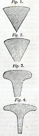
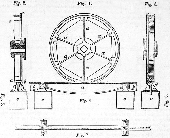
many years. The rails or bars which I have invented are formed as
prisms, though their sides need not of necessity be flat. Figs. 1
and 2 show sections of the bar thus formed; the upper surface upon
which the wheel of the carriage is to run is slightly convex, in
order to reduce the friction; and the under part rests in the
supporting-blocks, chairs, rests, standards, or pedestals, which are
mounted upon the sleepers. The wedge-form is proposed, because the
strengths of the rail is always in proportion to the square of its
breadth and depth. Hence this form possesses all the strength of a
cube equal to its square, with only half the quantity of metal, and,
consequently, half the cost. Sufficient strength, however, may be
still retained, and the weight of metal further reduced, by forming
the bars with concave sides, as shown in section, by Figs. 3 and 4. The mode of making iron bars of a great variety of forms, we have
already generally explained in our account of the iron manufacture.”
――――♦―――― |
|
FOOTNOTES |
|
1. |
‘Hammer blow’ refers to
the vertical forces transferred to the track by a locomotive’s
driving wheels. Although most is due to the unbalanced reciprocating
motion, which in slow-moving early locomotives would not have been
significant, the piston thrusts also contribute to it. The result is
that rails are subjected to an intense and regular pounding, which
can cause damage. |
|
2. |
There is some dispute
over the invention of cast-iron rails. They are generally credited
to John Curr, being first used underground in mines at Sheffield c.
1776, only later being used overground. Another claim is that
cast-iron rails were used at Coalbrookdale c.1768. |
|
3. |
“The
cast-iron waggon wheel was really a north-country invention. As
early as may, 1731, Elias Thornhill of Sunderland, whitesmith,
obtained a grant of a patent for ’his new invention of making the
rim or edge of coal waggon wheels with iron or steel and with iron
ribs or tabbs and iron bolts, rivets, and screws for the fastening
the same.’ (Archaeologia Aeliana, vol. xxiv., p. 226)”
The North Eastern Railway,
William Weaver Tomlinson (1915). |
|
4. |
Commenting on the
Dowlais-Merthyr railway, William Taitt of Dowlais wrote on 17th
March 1791:
“We are now making Rails for
our own Waggon way which weigh 44 li or 45 li [pounds]
per yard. The Rails are 6 feet long, 3 pin
holes in them, mitred at the ends, 3 Inches broad Bottom, 2½ In. top
& near 2 In. thick . . . .”
The rails were spiked to
transverse wooden sleepers. |
|
5. |
The Pen-y-Darren
tramroad was a single track plateway with a gauge of 4 feet 4 inches over
the flanges of the L-shaped cast-iron plate rails, or 4 feet 2 inches
between the inside of the flanges. The plates were 3 feet long,
weighed 56 pounds each, and were spiked to rough stone blocks about 18
inches square. |
|
6. |
Most writers on this
subject credit Jessop with the first use of the iron edge rail, but
flanged wheels on wooden rails were in use in the North East of
England well before:
“The flanged cast-iron wheel had been used in the North of England
for half a century before Jessop introduced the iron edge rail, and
was not only mentioned by Bishop Pococke in 1760, but described and
illustrated in 1765 by Monsieur Jars, who actually gives the depth
of the flange, viz., from an inch to an inch and a half (Voyages
Métallurgiques, vol i., p.202). . . . The flanged waggon wheels had
merely to be transferred from the wooden to the iron rails when the
latter were laid down.”
The North Eastern Railway,
William Weaver Tomlinson (1915). |
|
7. |
Following Outram’s
death in 1805, ‘Benjamin Outram and Company’ was rename the
‘Butterley Company’, and continued trading (as an engineering
company) until 2009. |
|
8. |
Malleable iron is a
form of cast-iron that is easier to work with than pure iron. It is
made by melting scrap steel and pig iron and then carefully
controlling the cooling of the mixture over many hours. This results
in an iron that is very tough but not brittle. |
|
9. |
In metallurgy: work
hardening is the increase in hardness of a metal induced,
deliberately or accidentally, by hammering, rolling, drawing, or
other physical processes. |
|
10. |
“One
point, however, deserves particular notice here, as likely to be
attended with the most important advantage to the railway system,
which is the application of malleable iron instead of cast-iron
rails. Three miles and a half of this description of railway have
been in use for about eight years on Lord Carlisle’s works, at
Tindal Fell, in Cumberland, where there are also two miles of
cast-iron rail; but the malleable iron road is found to answer better in
every respect. Experiments with malleable iron rails have also been
made at Mr. Taylor’s Works, at Ayr, and Sir John Hope’s at Pinkie;
and, upon the whole, this method, as in the case of the Tindal Fell
Railway, is not only considerably cheaper in the first cost than the
cast-iron railway, but is also much less liable to accident. In the
use of malleable iron bars, the joints of the railway are
conveniently obtained about twelve feet apart, and three pedestals
are generally between each pair of joints.”
Report of a Proposed Railway from
the Coal-field of Mid-Lothian to the City of Edinburgh p.26
(1818). |
|
11. |
Soon to enter
partnership with the Stephensons in the Newcastle locomotive
manufacturing firm of Robert Stephenson & Company. |
|
12. |
George Stephenson to
William James, postmarked 20th December, 1821:
"With respect to the Stockton and
Darlington Railway Company advertising for cast-iron rails, it was
merely to please a few of the subscribers who have been brought over
by some of the cast-iron founders, but they have only advertised for
one-third to be cast-iron."
The Two James’s and the Two Stephensons ( 1861) p. 48. |
|
13. |
“The specifications for the malleable iron rails prescribed that
they should be fifty-six pounds per double yard; that the breadth of
the top of the rail should be two and one-fourth inches, and the
depth at the end two inches; that the depth at the middle should be
three and one-fourth inches; that the depth at the top flange should
be three-quarters of an inch; that the thickness of the web at the
top should be three-quarters of an inch; that the thickness of the
web at the bottom should be half an inch; that the edge should be
rounded and the surface flat; that the rails should be perfectly
straight, and fit to the chairs accurately; and that a sample rail
and chair, or patterns thereof, should be furnished to the company.”
A History of the Stockton and
Darlington Railway, J. S. Jeans (1875). |
|
14. |
“The weight and dimensions prescribed for the cast-iron rails and
accessory chairs were as follow:― ‘The length of each rail to be 4
feet, cast from good pig-iron; the weight per double yard to be 115
lbs.; the weight of the chairs to be 10 lbs. each, or 15 lbs. per
double yard; the breadth at the top of the rail to be 2¼ inches; the
depth at the end to be 4 inches; the depth at the middle to be 6
inches; the depth of the top flange to be 1 inch; the thickness of
the web at the top to be five-eighths of an inch.’”
A History of the Stockton
and Darlington Railway, J. S. Jeans (1875). |
――――♦――――
|