|
NOTES AND
EXTRACTS
ON THE HISTORY OF THE
LONDON & BIRMINGHAM RAILWAY
CHAPTER
12
DEVELOPMENT
OF THE STEAM
LOCOMOTIVE (II).
A QUESTION OF MOTIVE POWER
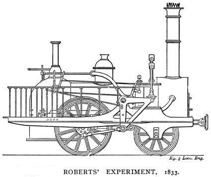
“Apart from three designed by Trevithick,
only 25 other locomotives had been built by 1823 and not one of them
was decisively superior to horse traction. The slow progress in
achieving a decisive breakthrough in the performance of the
locomotive resulted in the Stockton and Darlington Railway using a
mixture of stationary engines, locomotives and horse traction for
working the regular traffic . . . . After the superiority of the
locomotive had been demonstrated on the Liverpool and Manchester
Railway in 1830 the promoters of new lines had little difficulty in
raising the necessary capital.”
The Transport Revolution from 1770,
Philip S. Bagwell (1974).
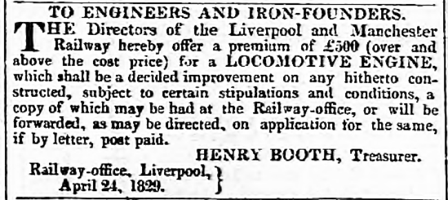
Birmingham Gazette,
Monday, 4th May 1829.
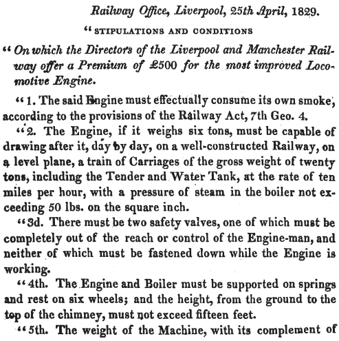
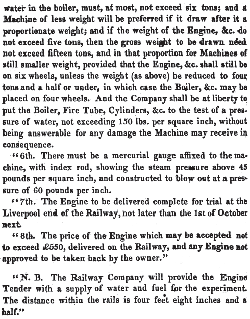
. . . . thus was announced the £500-prize that gave birth to the Rainhill
Trials, one of the most influential events in the history of
transport. The “certain
stipulations and conditions” the advertisement referred to were:
|
 |
|
 |
|
From A Practical
Treatise on Rail-roads, Nicholas Wood (1838). |
As the Liverpool and Manchester Railway neared completion, its
directors were faced with the decision on how the line was
to be worked:
“At that time the prospects of the
locomotive were most discouraging. The speed of five or six miles
per hour attained on the Killingworth and Darlington lines by no
means justified an enthusiastic support of the travelling engines. It was true that they had not been built with a view to speed, but
for the purpose of obtaining cheap carriage for coals. Indeed, not
many years before, the problem had been to make them move at all. But progression having been accomplished, the next thing was to
increase their powers.”
The Life of Robert Stephenson,
F.R.S., J. C. Jeaffreson (1864).
Steam locomotives had indeed acquired a poor reputation for
performance and reliability, added to which the highly inefficient boilers of the
time wasted large amounts of fuel. On a relatively short colliery wagonway, where
coal was cheap and
plentiful, a heavy fuel consumption was of little consequence, but
elsewhere the fuel bill had to be taken seriously. When
considered together, these factors
meant that locomotives were unlikely to be a practical proposition
for the immediate future, whereas both horse traction and stationary
steam engines
operating cable haulage were well-known quantities. Faced with this
conundrum, a party
of the line’s directors set out to visit the railways in the North-East
to assess the situation for themselves. What they saw merely
demonstrated that for the volume of traffic that they anticipated horse traction was out of the question, but they remained undecided
on whether to adopt
locomotives or cable-haulage.
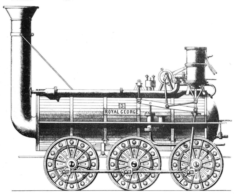
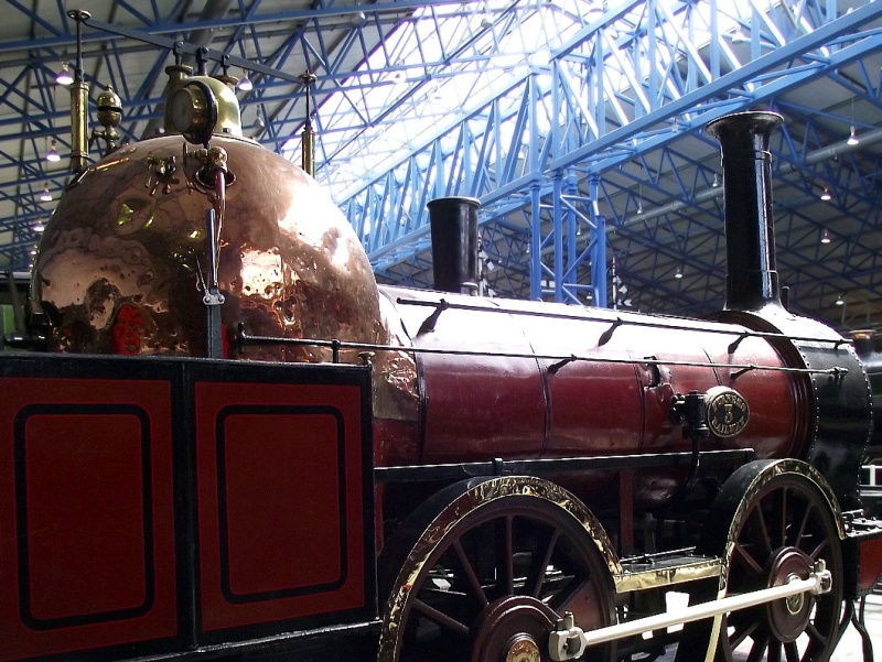
The ‘Royal George’ (1827), Stockton
and Darlington Railway.
Generally considered to be the first
adequate locomotive adapted to the rigours of everyday use,
and the
first to incorporate a correctly aligned steam blastpipe.
In view of their continuing indecision the Board decided to obtain a professional opinion independent
of their own advisors (principally the Stephensons, who were both keen advocates of
steam locomotives). To provide it they
engaged two eminent civil engineers, John Rastrick and James Walker. [1]
In January 1829, the pair set out on a
second tour of the North-East, their primary object being to
establish . . . . The comparative expense of conveying goods upon
a Railway by locomotive and by fixed Engines. [2] During their
tour, they gathered much information, included in which was an
interesting summary of the loads that locomotives were then capable
of hauling, Hackworth’s Royal George (above) being well
ahead of the field:
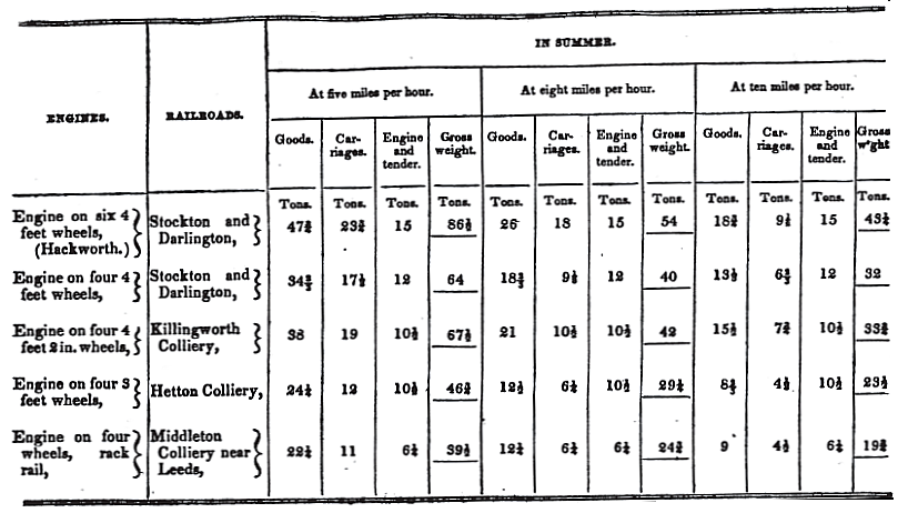
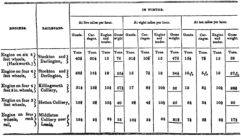
A Practical Treatise on
Rail-roads, Nicholas Wood (1838).
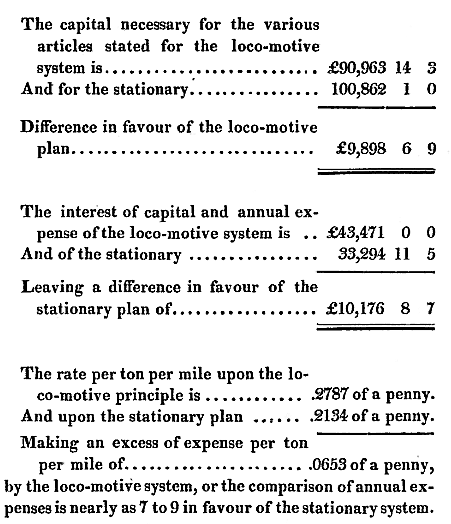
Rastrick and Walker submitted their findings to the Liverpool
and Manchester Board in
March 1829. In their report they provided their principals with a
considerable weight of data and calculations, which demonstrated
that, in terms of the cost of conveying each ton of goods per mile, a system of fixed engines would
be cheaper to operate than locomotives. However, they did acknowledge that the choice between the two forms of
motive power was finely balanced.
In his summary of the study,
Henry Booth, Secretary to the Liverpool and Manchester Railway
Company, had this to say:
“The advantages and disadvantages of each
system, as far as deduced from their own immediate observation, were
fully and fairly stated, and in the opinion of the engineers
themselves, were pretty equally balanced. The cost of an
establishment of fixed engines between Liverpool and Manchester,
they were of opinion, would be something greater than of locomotives
to do the same work; but the annual charge, including interest on
capital, they computed would be less on a system of fixed engines
than with locomotives. The cost of moving a ton of goods thirty
miles, that is from Liverpool to Manchester, by fixed engines, they
estimated at 6.40d., and by locomotives at 8.36d., supposing in each
case a profitable traffic both ways.”
The Life of Robert Stephenson,
F.R.S., J. C. Jeaffreson (1864).
Liverpool and Manchester
Railway. Report to the Directors, James Walker (1829).
In arriving at their costings, Rastrick and Walker worked on the
basis of the following scheme of stationary engines:
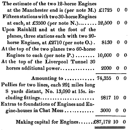
Liverpool and Manchester
Railway. Report to the Directors, James Walker (1829).
When it came to dealing with the likely fuel cost for operating the
line with locomotives, the
consultants experienced a difficulty:
“As to the consumption of fuel by
locomotive Engines: This article is so cheap in most places where
locomotive Engines are in use, that it is not customary to keep any
accurate accounts of it . . . .”
Liverpool and Manchester
Railway. Report to the Directors, James
Walker (1829).
. . . . added to which was the effect of the significant difference
in the efficiency of locomotive boilers then in use, and hence their fuel
consumption. What figures could be obtained ranged between 1.6 and 3
pounds weight of coal per ton per mile.
However, the pair discovered that engine drivers on the Stockton and
Darlington Railway were required to pay for the coal they
used, which they assumed, not unreasonably, would
encourage them to exercise some economy in its use. The
railway company kept a record of the amount of coal they sold as well as the ton miles their locomotives
ran, which, taken together, suggested a fuel consumption of 2.8
pounds per ton per mile. In their calculations, Rastrick and
Walker reduced this to 2.5 pounds to take account
of known improvements that were then being made in boiler
efficiency, which produced an estimated annual fuel bill of £13,653 for a fleet
locomotives, compared with £3,784
for fixed engines and cable haulage. [3]
In their response to the Rastrick/Walker
report, Robert Stephenson and Joseph Locke conceded that fixed engines were inherently more efficient
than locomotives:
“It is probable that the consumption of
fuel by Locomotive Engines will always be greater than by Fixed
Engines. In the latter the heat may, without inconvenience, be
applied in the best possible manner, and care taken to prevent loss
of heat by radiation; but lightness, compactness, and simplicity
being absolutely necessary in Locomotives, we are compelled to adopt
less economical methods of applying the fuel.”
Observations on the comparative
merits of locomotive & fixed engines,
Robert Stephenson and
Joseph Locke (1830).
A further point raised by Rastrick and Walker was that even if locomotives were to be used,
they would be unable to cope with the two 1:96 gradients at Rainhill and Sutton,
which would at any rate require cable haulage. Subsequently, however, the Rainhill
Trials demonstrated that locomotives were capable of handling such
gradients unassisted, although cable haulage was inevitable on the
1:48 gradient to the dockside at Liverpool.
Despite its apparent cost advantage, some points of interest emerged
from the report that underlined the weaknesses of the cable system. The first concerned
the
initial capital outlay, where the ready ability to increase
the number of locomotives by incremental steps, in line
with traffic growth, gave locomotives a distinct advantage over the
inflexible alternative:
“If the quantity of goods be small or
uncertain, it would require no calculation to determine that the
locomotive system is the cheaper, because by it you increase the
power by an increase of the number of Engines, and can therefore
always proportion the power to the demand, while upon the stationary
system it is necessary first to form an estimate of the probable
trade, and then at once to establish a line of Engines, Ropes, &c.
from end to end, that shall be complete and fully equal to it. There
is therefore in the locomotive system an advantage in this respect,
that the outlay of capital may at the first be much less than by the
other system.”
Liverpool and Manchester
Railway. Report to the Directors, James
Walker (1829).
Another factor against cable was the higher impact on
traffic flow, compared with locomotives, resulting from a failure in
any of the sections of the line of
either the cable ― the most likely cause ― or the power
plant:
“The probability of accident upon any
particular part of the system is, I think, less with the stationary
than with the locomotive; but in the former the effects of an
accident extend to the whole line, whereas in the latter they are
confined to the particular Engine and its train, unless they happen
to obstruct the way and prevent others from passing. The one system
is like a number of short unconnected chains, the other resembles a
chain extending from Liverpool to Manchester, the failure of one
link of which would derange the whole.”
Liverpool and Manchester
Railway. Report to the Directors, James
Walker (1829).
But perhaps the most telling blow against cable was the recognition
that, after many years of development, principally under Watt, the
stationary steam engine had reached a relative plateau of refinement compared with
the steam locomotive, where there lay much unexploited potential:
“I have reasoned upon the Engines generally
in their present state, but it is proper to say that improvements
have, since my survey in 1824, been made in them, and that the
attention at present bestowed upon the subject will in all
probability still do much for them. The Engine made by Mr. Rastrick
is different from that by Mr. Hackworth in the form of the flue and
otherwise; Mr. Stephenson’s is different from both, and every new
Engine he makes, differs in some respects from the one preceding
it.― Since 1824 the diameter of the wheels has been increased,
wrought iron tire substituted for cast, spring safety-valves have
been introduced, and the Engine itself is supported upon a spring
carriage. I think all these decided and great improvements, and in
estimating the question generally it is fair to anticipate others.
It is true that improvements in the stationary system may also be
expected, but not, I should say, to the same extent.”
Liverpool and Manchester
Railway. Report to the Directors, James
Walker (1829).
No doubt influenced by these last three arguments and, despite their consultants’
overall recommendation, the Board remained
undecided on what motive power to adopt, although by now the steam
locomotive had gained a majority of supporters providing it
could be shown to be up to the job. Thus, the decision was taken to hold a competition.
――――♦――――
THE RAINHILL TRIALS.
“Considering the very important
conclusions, which have resulted from the competition, induced by
the offer above noticed, the very rapid improvement which it
produced in these engines, forming not only a new era in their
history, but in the importance of railway communication in general;
we shall make no apology, in giving a brief outline of the
proceedings, and of the various improvements effected by this
competition of talent.”
A Practical Treatise on
Rail-roads, and Interior Communication, Nicholas Wood (1838).
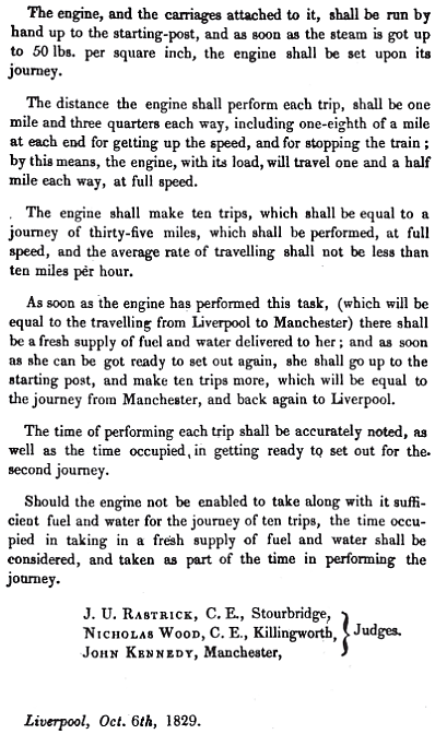
The trials were to take place on a section of level track, about
1¾-miles long, at Rainhill, a few miles to the east of Liverpool.
News of the event caused much excitement. Supporters of the steam
locomotive hailed it as an opportunity to create a great change in
internal communications, the Company’s shareholders saw it as a
scheme from which profit (or loss, depending on point-of-view) would
emerge, the canal companies saw it as a threat to the wellbeing of
their businesses ― in this they were correct ― and the public looked
on in anticipation of great entertainment and spectacle:
“On the morning of the 6th the ground at
Rainhill exhibited a very lively appearance; several thousand
persons were collected from all parts of the country, amongst whom
were several of the first Engineers of the day. A commodious tent
had been erected for the accommodation of the ladies, which was
graced by the beauty and fashion of the surrounding neighbourhood;
the sides of the race ground were lined with carriages of all
descriptions;― in short, the tout ensemble exhibited as much bustle
and excitement as if the great St. Leger had been about to be
contested.”
Observations on the comparative
merits of locomotive & fixed engines,
Robert Stephenson and
Joseph Locke (1830).
The competition was set to commence on the 6th October 1829. The three
judges were to be John Rastrick (civil engineer), Nicholas Wood
(viewer at Killingworth Colliery and writer on locomotive
engineering) and John Kennedy (a Manchester industrialist). Their
first task was to refine the competition rules:
“The original stipulations of the Directors
containing no regulations as to the mode of trying the powers of the
different engines, the judges determined, that in order to ascertain
the comparative merit of each they should be subjected to the
following practical test. And in consequence, a card, containing the
following regulations, was distributed to the different
competitors.”
A Practical Treatise on
Rail-roads, and Interior Communication,
Nicholas Wood (1838).
Much of what then took place during the Rainhill Trials is beyond
the scope of this chapter (some press reporting
of the event is reproduced at
Appendix I). Suffice it to say that of the six competition entries,
three did not compete or failed to meet the entry requirements; these were
the Manumotive, a type of rail carriage operated by two men, entered by Ross Winan; Thomas Brandeth’s Cycloped, which
was powered by two horses walking an endless belt; and Timothy
Burstall’s Perseverance, which looked similar to Ericson’s Novelty, but there the comparison ends,
for it failed to reach the stipulated minimum speed of 10 m.p.h.
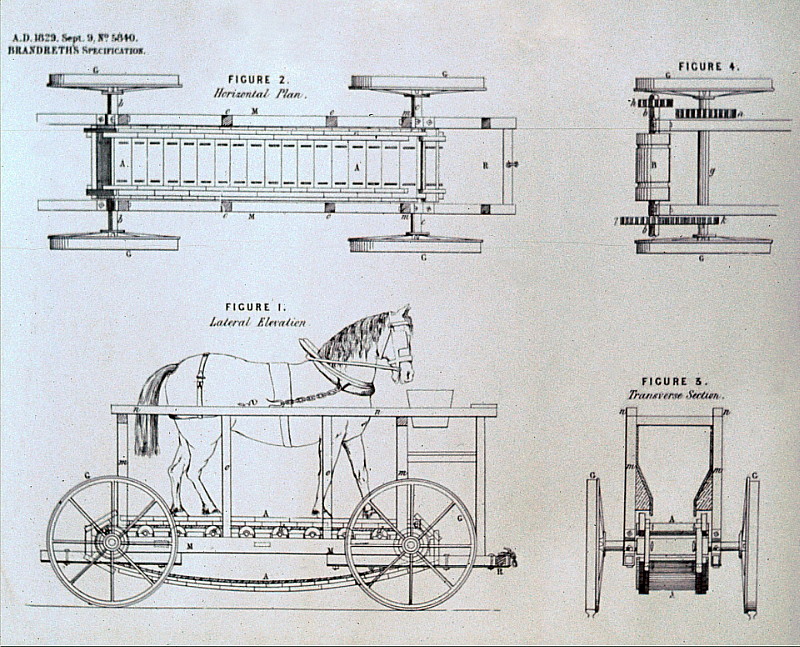
The Cycloped
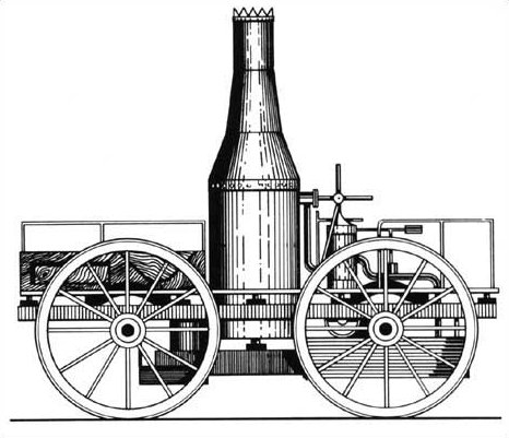
Perseverance.
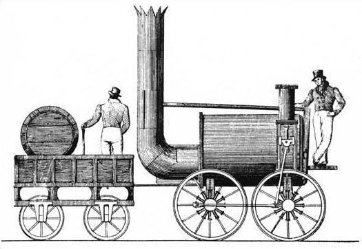
Of the remaining three entries, each being steam powered, only the Stephensons’ Rocket
completed the trials successfully. Timothy Hackworth’s
Sans Pareil [4] suffered boiler failure and the Novelty, entered
by Messrs. Ericsson and Braithwaite, was withdrawn following
a burst steam joint.
Although
Sans Pareil and Novelty [5] represented cul-de-sacs
in the evolution of mainstream steam locomotives, it worth saying something about them.
|
 |
|
 |
|
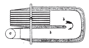
Timothy Hackworths San Pareil and
its return-flue boiler.
'C' marks the chimney, the parallel lines represent the
grate for the furnace. |
|
 |
|
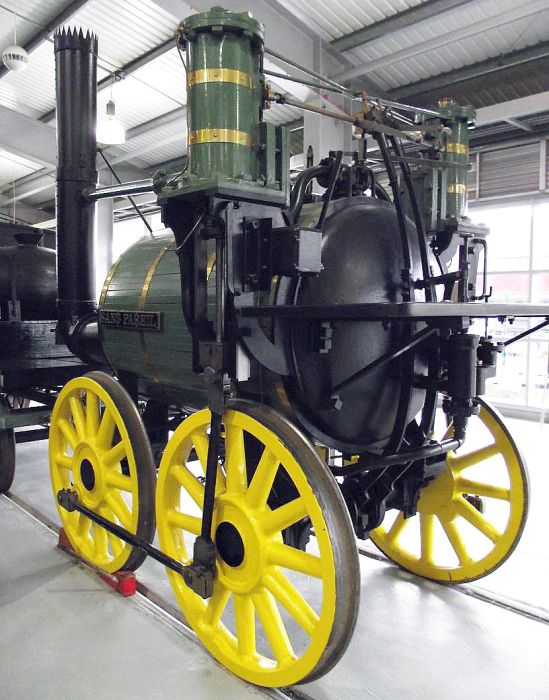
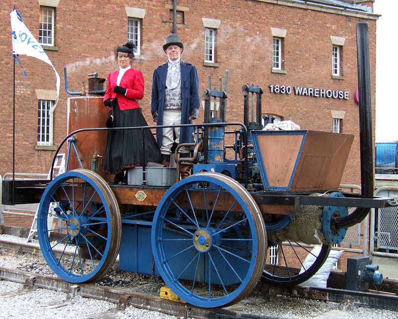
A replica of Timothy Hackworth’s
Sans Pareil on display at the
National Railway
Museum, Shildon. |
Sans Pareil (“without equal”) was a scaled-down version of Hackworth’s
Royal George. Fitted with wooden-spoked wheels (4 feet 6 inches
diameter) to save weight, the locomotive was powered by vertical cylinders
(7 inches diameter by 18 inches) that gave it the uncomfortable
rolling motion typical of its type. This instability would have limited its
in-service speed for passenger traffic (on the fifth trip of the
Trials the locomotive averaged 22.7 m.p.h., its best run) and its
vertical cylinders would probably have resulted in significant
hammer-blow to the track. Steam was produced in a
return-flue boiler (4 feet 2 inches diameter by 6 feet), the blast
being so fierce that it ejected a great deal of partly burned fuel
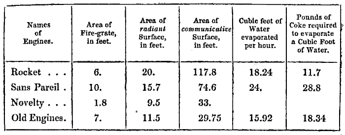
from the chimney resulting in heavy fuel consumption. Whereas the Rocket required 11.7
pounds of
coke to convert a cubic foot of water into steam, Sans Pareil
required 28.8 pounds:
The Engineer’s and
Mechanic’s Encyclopædia, Luke Hebert
(1836).
During Sans Pareil’s second appearance
in the competition, her boiler feed pump failed, the
level of water in
the boiler fell below the safe limit and the consequent increase in
temperature melted the fusible plug. Hackworth’s appeal to the judges for further time for
repairs was declined on the grounds of exceeding the
stipulated weight, which, together with the heavy fuel consumption,
precluded the judges from recommending the locomotive to the Company.
Nevertheless, Sans Pareil had a long life. After the trails she was bought by the Liverpool and
Manchester Railway and later sold to the Bolton and Leigh
Railway. In 1837, larger cylinders were fitted and her
wooden-spoked wheels replaced with cast-iron. In 1844, she was moved to the Coppull
Colliery near Chorley, turned into a stationary engine
and used to drive pumping and
winding equipment. Finally, in 1863, Sans Pareil was presented to the Patent Office Museum
(now the Science Museum), and later transferred to the
care of the National Railway Museum at Shilden where she is now on
display.
Overall, Sans Pareil was outmoded; whereas the Rocket
lay at the start of the evolutionary line that led to the
mature steam locomotive, San Pareil lay at the end of the
first era of locomotive development reaching back to Trevithick’s
Catch-me-who-can, to which she bore some resemblance.
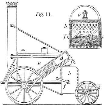
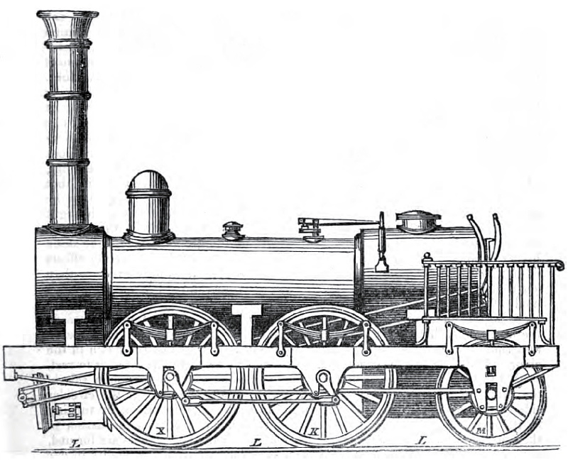
Braithwaite and Ericson’s
Novelty.
The Novelty represented what might best be described as an
interesting prototype, at a
time when the form and layout of the railway locomotive’s basic
components had yet to be settled:
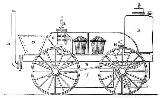
“Messrs. Braithwaite and Erickson’s engine,
the ‘Novelty,’ is of a different principle, the air being driven or
forced through the fire by means of a bellows. The accompanying
drawings will shew the general construction of this engine, and more
particularly the generator, or mode of raising the steam, which
constitutes its prominent peculiarity.”
A Practical Treatise on Rail-roads,
Nicholas Wood (1836).
The storage of fuel on the footplate and water in a well between the
wheels (viz. letter ‘T’ above) placed
Novelty in the category of what were later classed as ‘tank’
engines ― as, indeed, was Burstall’s Perseverance. Judging
from contemporary reports there can be little doubt that
Novelty was the decided favourite among the crowd:
“The great lightness of this
engine, (it is about one half lighter than Mr. Stephenson’s) its
compactness, and its beautiful workmanship, excited universal
admiration; a sentiment speedily changed into perfect wonder, by its
truly marvellous performances. It was resolved to try first its
speed merely; that is at what rate it would go, carrying only its
compliment of cote and water, with Messrs Braithwaite and Erickson
to manage it. Almost at once, it darted off at the amazing velocity
of twenty-eight miles an hour, and it actually did one mile in the
incredibly short space of one minute and 53 seconds. Neither did we
observe any appreciable falling off in the rate of speed; it was
uniform, steady, and continuous.”
Mechanics’ Magazine,
Vol. 12 (1830).
|
 |
|
Bell cranks being used
to convert vertical to horizontal thrust. |
In common with Sans Pareil, the drive in Novelty was
from vertically mounted cylinders. However, unlike Sans Pareil,
in which the vertical
cylinders were connected directly to the crankpins, the drive on
Novelty was via bell-cranks. These worked horizontal rods
connected to the cranked front axle, an arrangement that enabled a
leaf-spring suspension to be provided despite the locomotives’ cylinders
being vertically
aligned. Only the front axle was connected to the cylinders,
but the design did provide for both axles to be coupled using chain
drive.
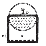
As Wood observed, the boiler was the locomotive’s “prominent
peculiarity”, having the appearance at first sight of a vertical
boiler. In fact the greater part of the boiler barrel extended
horizontally under the locomotive. This contained an S-shaped flue,
which carried the combustion gases from the furnace to the chimney at
letter ‘G’. Fuel was fed into the furnace (letter ‘F’ below) down a tube
(letter ‘C’), which passed through the boiler barrel (letter ‘A’), a method
later adopted by Sentinel in their steam wagons and shunting engines. In his design, Ericson bypassed the need for a blast
pipe by using forced draught, provided by axle-driven bellows, which
entered underneath the fire at letter ‘E’. Spent steam was
exhausted directly into the atmosphere.
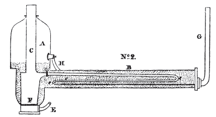
The Novelty’s boiler.
Although withdrawn from the trials due to boiler failure,
Novelty performed more successfully than San Pareil. The
first day of the trials was taken up with some demonstration runs. According to the Morning Post (9th October 1829), “the
speed of all the other locomotive steam-carriages on the course was
far exceeded by that of Messrs. Braithwaite and Co.’s beautiful
engine from London. It shot along the line at the amazing rate of
thirty miles in the hour.” On the second day of the Trial, the
locomotive ran under test conditions:
“‘The Novelty’ engine of Messrs.
Braithwaite and Ericsson was this day tried with a load of three
times its weight attached to it, or 11 tons 5 cwt.; and it drew this
with ease at the rate of 20¾ miles per hour; thus proving itself
to be equally good for speed as for power. We took particular notice
to day of its power of consuming its own smoke, and did not any time
observe the emission of the smallest particle from the chimney.”
Mechanics’ Magazine,
Vol. 12 (1830).
Novelty next appeared on the fifth day of the trials, but did not
run under test conditions. During the morning the failure of some
pipework required repair, but the locomotive reappeared in the afternoon,
at the conclusion of which:
“Another carriage with seats for the
accommodation of passengers, was now substituted for the loaded
waggons attached to ‘The Novelty,’ and about forty-five ladies and
gentlemen ascended to enjoy the great novelty of a ride by steam. We
can say for ourselves that we never enjoyed any thing in the way of
travelling more. We flew along at the rate of a mile and a half in
three minutes; and though the velocity was such, that we could
scarcely distinguish objects as we passed by them, the motion was so
steady and equable, that we could manage not only to read but write
. . . .”
“. . . . A fresh pipe had, it appeared,
been substituted for the one which failed on the preceding trial;
one or two other parts of the machinery that were in a faulty state,
had also been renovated; but the engine, with the exception of some
of the flanges of the boiler being as Mr. Ericsson expressed it,
rather green, was pronounced in a working state . . . . The engine
now started to do the 70 miles for a continuance; but just as it had
completed its second trip of three miles, when it was working at the
rate of 15 miles an hour, the new cement of some of the flanges of
the boiler, yielded to the high temperature to which it was exposed,
and the spectators had again the mortification to hear it announced
that it was, under these circumstances, impossible the trial could
go on.”
Mechanics’ Magazine,
Vol. 12 (1830).
And that concluded the Novelty’s appearance at the Rainhill
Trials. In their account of the event, Messrs. Stephenson and Locke
give a more detailed analysis of the boiler failure:
“The first trip of 3 miles was performed in
16’ 43” which is at the rate of 10¾ miles an hour. In the second
trip the pipe which conveys the heated air from the furnace through
the horizontal boiler collapsed, and the steam, forcing its way into
the fire place, was evolved from the bottom of the furnace into the
atmosphere. This failure was at the time attributed to the yielding
of a ‘green joint,’ and was considered as such by the Judges; but
having seen the pipe when it was taken out, we feel convinced that
its failure alone was sufficient to account for the accident,
without the addition of any joint giving way.
The ‘Novelty’ was then withdrawn and Mr. Hackworth requested that he
might be allowed another trial. The Judges refused, on the ground
that his Engine was not only above weight, but that it was on such a
construction as they could not recommend to the Directors of the
Company.”
An Account of the
Competition of Locomotive Engines at Rainhill,
Robert Stephenson and Joseph Locke (1830).
A replica of Novelty.
Although in some ways an ingenious design, a locomotive of
Novelty’s design could not have been scaled up sufficiently to meet the more
demanding loads
that locomotives would shortly be called upon to haul, and over
greater distances. Furthermore,
the double-return boiler flue would have been impossible to clean
unless it had been constructed in sections to permit dismantling,
and only then with difficulty.
Following the Rainhill Trails, the locomotive ran experimentally on
the line before being transferred to the St. Helens and Runcorn Gap
Railway, where in 1833 she received a new boiler and cylinders. In
1838, Novelty is known to have been used on the construction
of the North Union Railway, after which she disappears from history.
Having met the competition criteria,
the £500 prize was shared between Henry Booth, on account of his
contribution to the Rocket’s boiler design, and the locomotive’s
designers and builders, the Stephensons. Had the Novelty not
suffered boiler failure, the outcome of the competition might have
been different, despite that locomotive’s unsuitability as a platform
for future development.
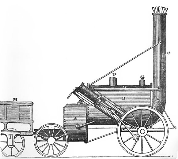
The Rocket, together with a
cross section of her firebox.
See also
Appendix II.
|
Built to compete in the
Rainhill Trials, under test Rocket beat its competitors
with its top speed of 29 mph and better reliability,
thereby confirming its designer, Robert Stephenson, as
one of the premier mechanical engineers of his age. |
“The furnace at A is a square box,
about 3 feet wide and 2 feet deep. This furnace has an external
casing, between which and the fireplace there is a space of 3 inches
filled with water, and communicating by a lateral pipe with the
boiler. The heated air, &c. from the furnace passes through
twenty-five copper tubes, 3 inches in diameter, arranged
longitudinally on the lower half of the boiler, and then enters the
chimney C. D represents one of the two steam
cylinders, which are placed in an inclined position on each side of
the boiler, and then enters the chimney C. D
represents one of the two steam cylinders which are placed in an
inclined position on each side of the boiler, and communicating by
their piston rods, through the media of connecting rods E, motion to
the running wheels. P G are safety valves; E is one of
two pipes on each side of the boiler, by which the eduction steam
from the cylinders is thrown into the chimney, and by the exhaustion
thus caused in the latter, producing a rapid draft of air through
the furnace. At M is exhibited part of the tender, which
carries the fuel and water for the supply of the engine.”
A Practical Treatise on
Rail-roads and Locomotive Engines, Luke
Hebert (1837).
The Rocket was built by Robert Stephenson & Co. at the firm’s
Newcastle-upon-Tyne works (see
Appendix II. for technical details). Although lack of hard
evidence makes it impossible to say who designed the locomotive, it
was probably a collaborative effort. The locomotive brought together a number of
engineering features ― some new, some existing ― which, taken together, represented a step change in locomotive design,
on the back of which further important developments were soon to
follow.
The
reasons for the Rocket’s high performance during the Rainhill
Trials can be attributed to a separate firebox, multiple fire-tube boiler and blastpipe,
which,
acting together effectively, resulted in material
improvements to the locomotive’s steam-raising ability and thermal
efficiency, while moving the connecting rods towards the horizontal
improved its suspension:
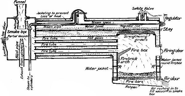
The principle of the fire-tube
locomotive boiler.
Combustion takes place in the firebox, the hot gases then passing
through the boiler to the smoke box
along numerous fire-tubes.
|
 |
|
The Rocket showing
(top right) firebox,
water jacket and fire tubes. |
Separate firebox. In locomotive designs
predating Rocket, the furnace was located
at one end of the boiler flue. Early attempts to use a blast pipe to intensify the fire
when the locomotive was under load often created such a strong current of air through the fire,
that it was torn, causing large amounts of incompletely burnt fuel to be
expelled along the flue and up the chimney. Such was the experience with
the Sans Pareil
during the Rainhill Trials, which in part accounted for her very
heavy fuel consumption. The introduction of the
external firebox in the Rocket, provided a separate combustion chamber of larger
volume and grate area that had been possible when the fire was
confined within the boiler flue. The result was more complete
combustion, which was further improved following the invention of
the firebrick arch (attrib. Griggs
ca. 1856) shown in the drawing above [6]. Furthermore,
because the firebox was shrouded in a
water-jacket (except at its base where the grate bars were located),
some 20 square feet of water was exposed to the most
intense heat:
“The area of surface of water, exposed to the radiant heat of the
fire, was 20 square feet, being that surrounding the fire-box or
furnace; and the surface exposed to the heated air or flame from the
furnace, or what we shall call communicative heat, 117.8 square
feet; the area of the grate bars being 6 square feet. The end view
[adjacent drawing], will shew the disposition of the tubes in
the end of the boiler, with the fire box surrounding the end.”
A Practical Treatise on
Rail-roads, Nicholas Wood (1838).
Cool water entered the firebox jacket from the bottom
of the boiler through pipes on either side, while hot water left the
top of the jacket through a further pipe to the top of the boiler,
thus allowing thermal circulation between the two.
Multiple fire-tube boiler. Twenty-five
3-inch diameter tubes conveyed the combustion gases from the furnace
through the boiler. This arrangement replaced the single or return
flue (or in the case of the Lancashire Witch, parallel flues)
of earlier locomotive boiler designs, and greatly increased the
heating area to which the water in the boiler was exposed.
Multiple fire-tubes gave the boiler a far greater steam-raising
capacity ― thus avoiding a problem suffered by early locomotives,
which often ran out of steam and had to halt until boiler
pressure was restored ― and by utilising more of the heat to produce
steam, rather than wasting it up the chimney, less fuel was used per
cubic foot of water evaporated:
“In the Rocket the surface exposed to the
radiant heat of the fire compared with the area of the fire grate is
as 3⅓:1, while in the Sans
Pareil [return-flue boiler] it is only 1½:1, the same
proportion as in the old engines. In the Rocket, the surface exposed
to the heated air and flame, compared with the area of the
fire-grate, is as 19⅔:1; while
in the Sans Pareil, the proportion is only 7½:1.
The bulk of air passing through the tube of the Sans Pareil, at its
exit into the chimney, is 176.7 square inches, the exposed surface
being 47.12, or 3.8:1 nearly; while, as before stated, the bulk of
air passing through the tubes of the Rocket is 176.7 inches, or
precisely that of the Sans Pareil, while the surface exposed is
235.6 inches or 1⅓:1. These will
sufficiently account for the great difference in the evaporating
powers of the two engines, and also in the economy of fuel; the
Rocket requiring only 11.7 lbs to convert a cubic foot of water into
steam, while the Sans Pareil required 28.8 lbs.”
A Practical Treatise on
Rail-roads, Nicholas Wood (1838).
The multiple fire-tube boiler became a standard feature in
locomotive boiler design, but who can claim credit for its invention
is uncertain. Although Henry Booth is credited with suggesting its
use to George Stephenson, the French Engineer Marc Seguin
(1786-1875) patented the idea in 1827 and in 1829
built a locomotive that utilised it. The English inventor James
Neville is another claimant, while in the U.S.A. John C. Stevens
patented a water-tube boiler in 1803.
Blastpipe. In early
locomotives back to the time of Trevithick, it had been observed
that by turning the exhaust steam from the locomotive’s cylinders up
the chimney, a partial vacuum was created in the base of the chimney that air
rushed in to fill through the furnace grate and the boiler flue. This
inrush of air fed more oxygen to the fire, thereby intensifying it, a
beneficial effect and one that increased in proportion to the load on the
locomotive. However, it was not until the
introduction of the separate firebox in combination with the multitubular boiler
that the blastpipe became really effective, and a standard feature
in locomotive design.
Inclined cylinders. Moving the Rocket’s cylinders from
the vertical position adopted on most old locomotives ― Trevithick’s
early road and rail locomotives being notable exceptions ― to
35º to the horizontal, allowed
spring suspension to be installed, which improved the distribution
of the locomotive’s weight on the track. Shortly after Rainhill locomotives
appeared with their cylinders installed near to the horizontal,
which together with spring suspension became standard practice.
――――♦――――
DEVELOPMENTS FOLLOWING
THE RAINHILL TRIALS
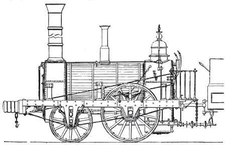
The Northumbrian, Robert
Stephenson & Co. 1830.
Following the Rainhill Trials, almost a year elapsed until the
official opening of the Liverpool and Manchester Railway took place on the 15th
September, 1830. In the intervening period, Robert Stephenson & Co.
built seven locomotives for the Railway on similar lines to the
Rocket, one being the Northumbrian pictured above. These locomotives [7] differed from the Rocket
in several ways. They were at least 3 tons
heavier, but the most significant change was to the water
jacket/firebox, which was integrated with the boiler. With the
addition of a separate smoke box, these became standard design
features in
locomotive boilers for the remainder of the steam traction era. Other features built in to this ‘improved Rocket class’ were
changes to the firetubes (reduced in size from 3 inches in the
Rocket to 2 inches and increased in number from 25 to 90) and a
reduction in the angle of the cylinders to near the horizontal. Apparently in the Rocket . . . .
“The steep inclination of the outside
cylinders caused the pistons to lift and depress the engine upon the
springs at every double stroke, and at moderately high speeds the
unsteadiness thus occasioned was very considerable. Timothy
Hackworth appears to have been the first to decide upon the
arrangement so widely adopted afterwards, for securing steadiness at
high speeds ― to wit, horizontal inside cylinders and a cranked
driving axle.”
Locomotive Engineering, and the
Mechanism of Railways: Vol. 1,
Zerah Colburn, Daniel Kinnear
Clark (1871).
Purpose-built tenders also made their first appearance, and both
locomotive and tender acquired buffers ― leather stuffed with horse
hair.
The Planet represented the next locomotive type to emerge
from the works of Robert Stephenson & Co. Not only did it give its
name to the 2-2-0 wheel arrangement, but it became the first design to
be built in quantity and to acquire something approaching the outward appearance of the
steam locomotive in its maturity. Although the Planet represented a further step change in locomotive design, in common
with the Rocket before it most of its refinements
were a bringing together of existing ideas enhanced with suggestions made by
others.
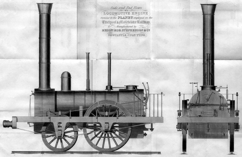
Planet-class
locomotive, Robert Stephenson & Co., 1830.
“The improvements which had been made in
the ‘Planet’ were very conspicuous. They were, in fact, the
combination in one engine of what had previously been known; viz.
the blast pipe, the tubular boiler, the horizontal cylinders inside
the smoke-box, and the cranked axle, together with a fire-box firmly
fixed to the boiler. The ‘Rocket’s’ fire-box was only screwed
against the boiler, allowing a great leakage of air which had not
passed through the fire.”
A Practical Treatise on Railways,
Peter LeCount (1839).
“Since
the opening of the Liverpool and Manchester line, experience has
suggested a great variety of improvements, which have considerably
increased the power and speed of the engines;― of these the
following are the principal. The inclosure of the boiler
within wood, to prevent the radiation of heat;― the removal of the
cylinders from the exterior of the boiler to within a casing or
chamber which was kept warm by its proximity to the boiler, and by a
current of heated air from the boiler tubes;― the alteration in the
situation and motion of the piston rods from the exterior of the
wheel to beneath the boiler, and their connexion with two cranks
placed at right angles on the axles of the great wheels;― and the
production of a powerful draught, by forcing the steam which has
worked the pistons through an orifice up the chimney. By all
these improvements the three following important results are
obtained. 1st.― The unlimited power of draught in the furnace by
projecting the waste steam into the chimney;― 2nd. the unlimited
abstraction of heat from the air passing through the furnace;― and
3rd, keeping the cylinders warm, by immersing them in the chamber
under the chimney.”
Osbornes’
Guide to the Grand Junction, or Birmingham, Liverpool, and
Manchester Railway,
E. C.
Osborne (1840).
Rocket-type locomotives had an 0-2-2 wheel arrangement; the
smoke box was positioned above the driving wheels, while the heavier
firebox sat over the trailing wheels. In the Planets, the
position of the axles was reversed to give a 2-2-0 wheel arrangement. [8] This resulted in more weight being placed over the driving wheels,
which in turn gave more adhesion than in the
Rocket-class. The cylinders, which were almost horizontal, were placed inside the frames where they drove a cranked
axle, a layout that was to be followed in many other designs
throughout the steam era. However, the cranked axles of the day were
prone to failure due to difficulties in their manufacture; were a
fracture to occur, a locomotive could collapse on its broken axle. Stephenson took this risk into account by providing the Planets
with double frames; not only was the engine built around a solid
wooden frame reinforced with iron plate ― visible in the drawing
above holding the external bearings ― but a sub-frame was provided,
the driving wheels being mounted on two sets of bearings between the
two. Thus, were the cranked axle to fail, the driving wheels would
remain held in place.
The Planets also incorporated Richard Trevithick’s final contribution to the
development of the steam locomotive, his suggestion that heat loss
would be reduced by placing the
cylinders within the smokebox:
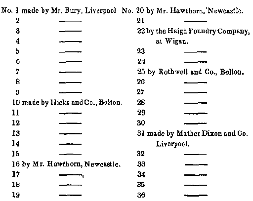
“The first eight engines made by Mr.
[Robert] Stephenson on the Liverpool and Manchester railway, viz.
the ‘Rocket’, ‘Meteor’, ‘Comet’, ‘Arrow’, ‘Dart’, ‘Phoenix’, ‘North
Star’, and ‘Northumbrian’, had the cylinders outside the boiler, and
worked by a crank pin on the wheel. Mr. Bury’s engine the
‘Liverpool’, was then constructed for that railway, and about four
months after it had been placed upon the line, Mr. Stephenson
adopted the crank axle, [9] and
placed the cylinders horizontally, with the improvement of putting
them inside the smoke-box. This was done first to his engine, the
‘Planet’, and it was suggested by a conversation which Mr.
Stephenson had with Trevithick, when they were on their passage from
South America. Trevithick stated there was 40 per cent increase in
the duty of Watt’s engines (worked expansively) in Cornwall from
putting a jacket on the cylinders.”
A Practical Treatise on Railways,
Peter Lecount (1839).
Finally, the Planets acquired a feature that was to become
standard practice in locomotive boiler design, the ‘steam dome’. Its purpose was to provide sufficient space to keep
the opening of the main steam pipe well above the water level in the boiler,
thereby preventing
water from being carried over into the cylinders and cause a condition known
as ‘priming’. Were this occurs, priming can damage cylinder lubrication
and (because water does not compress) result in split cylinders.
“The ‘Planet’, by Messrs. Stephenson,
undoubtedly presented the first combination of the horizontal
cylinders and cranked axle with the multitubular boiler; and the
cylinders were furthermore encased in the smoke box, and thus warmed
by the waste heat escaping from the tubes ― an arrangement suggested
to the late Mr. Robert Stephenson by Richard Trevithick. The
constructors of the ‘Planet’, from their established position and
long practice in engine making, were enabled to turn to good account
the plans and suggestions of Messrs. Hackworth and Kennedy, who had
formerly occupied responsible positions in the Newcastle factory,
and who still maintained a friendly if not intimate intercourse with
their old employers. It must be admitted, to the credit of both the
gentlemen just named, as well as to Messrs. Stephenson, that the
‘Planet’ was the prototype of the modern English locomotive and that
for many years it was the model from which both British and American
locomotive engineers copied, not only freely, but minutely. The
‘Planet’ was tried for the first time on December 4, 1830, and drew
a train of goods and passengers, weighing 76 tons, exclusive of
carriages and wagons, from Liverpool to Manchester in 2 hours 39
minutes, the highest speed on a level being 15½ miles an hour. The
engine, with coke and water, weighed 9 tons, the tender weighing 4
tons. The cylinders were 11 inches in diameter; the stroke of
pistons was 16 inches; the driving wheels were 5 feet in diameter,
and the leading wheels 3 feet. The boiler was 3 feet in diameter,
and 6½ feet long, the fire box presenting 37¼ square feet, and the
tubes 370 square feet of heating surface. The tubes were 129 in
number, and 1⅝ inches in diameter.
In the ‘Planet,’ then, the Locomotive Engine had assumed a definite
and permanent form compatible with a fair degree of speed and
tolerable economy in working. This single engine embodied the
results of numberless efforts at locomotive improvement, ― for
Trevithick’s machine of 1804, crude as it was, was nevertheless a
locomotive engine, needing only improvement, and in the direction
indicated with tolerable distinctness by the inventor himself.”
Locomotive Engineering, and the
Mechanism of Railways: Vol. 1, Colburn and Clark (1871).
Although a fine design, the Planet type was soon to be
superseded by the Patentee, the first ever 2-2-2 locomotive
design [10] that in its essentials became the epitome of
the express passenger locomotive for many years.
The Planets suffered three particular problems that
the Patentee was designed to solve. At speed, the Planet’s short wheelbase gave a
very uneven ride added to which the greater weight placed over the
driving wheels, while providing better adhesion, resulted in a axle
load [11] that was as much as the lightly built permanent way of the
age could withstand. But increasingly heavy trains required greater motive
power; thus, the choice was to continue
building small 4-wheel engines and double (or triple) heading heavy trains
― a practice later followed on the London and Birmingham Railway ― or build more powerful locomotives
and spread the
increased weight over a third axle. [12]
Adding a third axle to the Planet type not only solved the
problems of stability and axle weight, but provided space for a larger boiler
and more power.
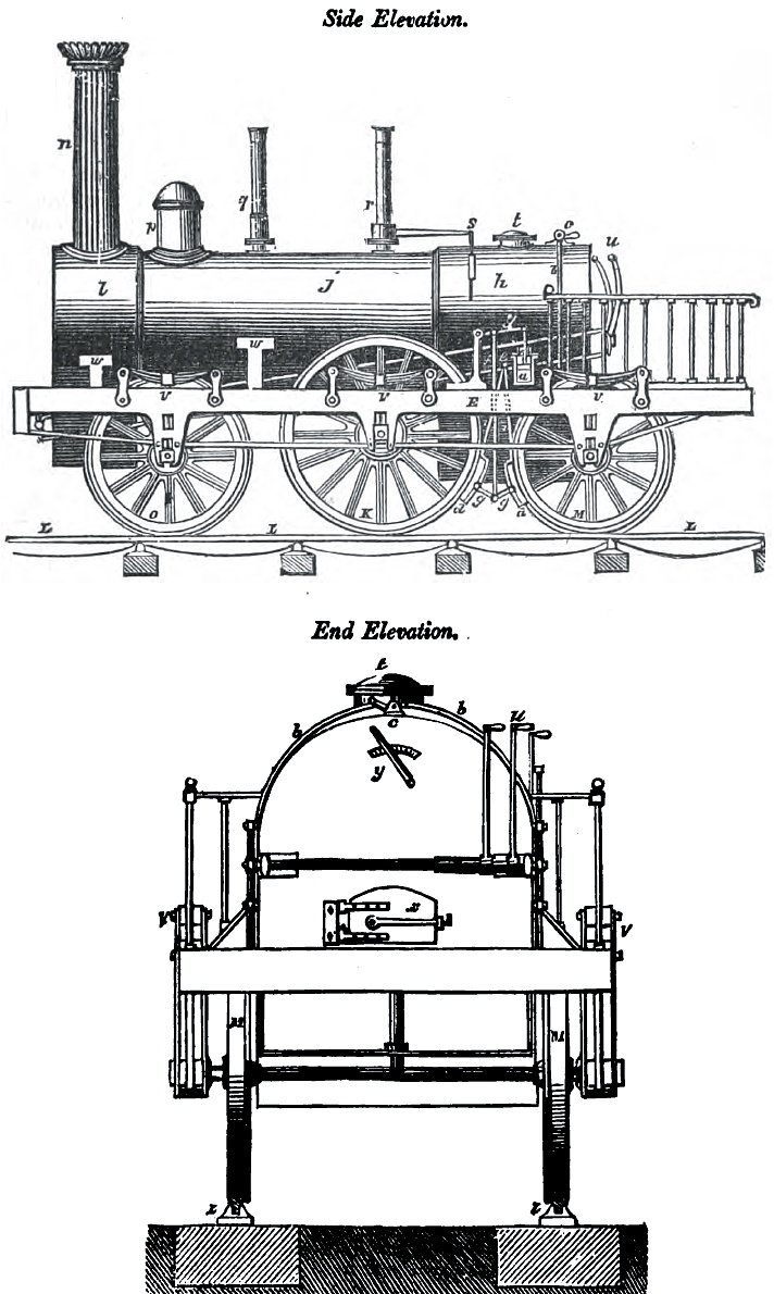
Robert Stephenson’s patent 2-2-2
locomotive.
“Locomotive engines, constructed according
to the description of the foregoing, Mr. Stephenson says, have the
effect of preventing the boilers being burnt out so soon as usual,
by allowing them to be made of greater magnitude and strength; the
additional wheels supporting the extra weight. The bearing springs
are used for the extra small wheels, the same as is now done for
other wheels in ordinary engines; the six springs used causing all
the six wheels to apply and bear fairly on the rails, and ease all
jolts and concussions; the relative weights, or portions of the
whole weight of the engine, which is to be borne by each of the six
wheels, being regulated by the strength and setting of their
respective bearing springs. The main wheels, which are impelled by
the power of the engine, are in all cases, left loaded with as much
of the weight of the engine as will cause sufficient adhesion of
those wheels to the rails, to avoid slipping thereon. The larger the
entire capacity of a boiler is, the more metallic heating surface it
will contain; and consequently, render unnecessary that extreme heat
which is so prejudicial to the metal. And that diminution of the
intensity of the combustion the patentee considers to be
advantageous in another point of view; because the jet of waste
steam (which is thrown into the chimney to produce a rapid draught
therein for exciting the combustion of the fuel) may be greatly
diminished in its velocity, which will permit the waste steam to
escape from the working cylinders with greater freedom than could be
permitted with smaller boilers, wherein a greater heat and a more
rapid generation of steam are indispensable to furnish the requisite
power.”
A Practical Treatise on Rail-roads
and Locomotive Engines, Luke Hebert (1837).
However, the addition of a third axle inevitably lengthened the locomotive’s rigid wheelbase,
which in turn increased
the stress on its (central) cranked axle when negotiating tight curves,
such as in sidings; and as
mentioned earlier, the cranked axles of the age had at any rate a tendency to facture.
Stephenson’s solution was to remove the flanges from the driving wheels. This gave them the ability to move laterally on sharp curves, thereby
relieving the stress on the cranked axle, while the flanged wheels on
the front and rear axles kept the locomotive on the track: [13]
“So considerable is the movement of the
driving wheels in such cases towards the inside of the curve, that
the flange of the inner wheel is often forced violently against the
rail. To this strain the frequent breaking of crank axles was
formerly attributed; and the late Mr. Robert Stephenson, in his six
wheel engine patent, based his claim upon the making of the driving
wheels with plain tyres, or tyres without flanges.”
Locomotive Engineering, and the
Mechanism of Railways: Colburn and Clark (1871).
A further innovation that Stephenson introduced was the
steam-powered brake. This was not a train braking system, but
applied only to the locomotive’s driving and trailing wheels (see
side elevation above ― the steam brake cylinder is at letter ‘a’). But the steam brake did not catch on and it was to be
some decades before steam braking was adopted.
The flangeless wheel and steam brake, together with other
improvements, became the subjects of a patent granted to Stephenson
in October 1833 ― hence the name given to the class locomotive,
Patentee:
A.D. 1833, October 7. ― No. 6484.
STEPHENSON, ROBERT. ―
Improvement, applying to that kind of locomotive carriage used on
the Manchester and Liverpool Railway (the first of which was called
the Planet), having the two main wheels fixed on a double-cranked
axle turned by the engine, to advance the carriage along the edge
rail. Makes the tyres of these main wheels without any projecting
flanges, and runs them plain upon the edge rails, and places beneath
the hinder end of the engine two small wheels with flanges on their
tires, to keep them straight on the rails.
2. A “brake or clog,” which is caused to press on the tires, by
means of a piston working in a small cylinder, supplied with steam
from the boiler.
3. Describes a locomotive engine carriage in present use (1833),
with the improvements added.
Patents for inventions.
Abridgments of specifications: Patent Office (1871).
The Patentee was completed at the workshops of Robert
Stephenson & Co. on 25th September 1833 and then delivered to the
Liverpool and Manchester Railway. [14] Other
locomotives of the Patentee type were constructed with 0-6-0
and 0-4-2 wheel arrangements:
“The following cut exhibits another form of
Mr. Stephenson’s locomotive engine, such as is now in use, but with
the foregoing improvement added thereto. The foremost wheels, at the
chimney end of the boiler, are, in this, however, impelled by means
of outside cranks and connecting rods, as well as the two middle
wheels K, [above] which are on the cranked axle; in other respects, the
improvement is the same as in the other engine. The brakes, or
clogs, are, of course, applicable to this or any other engine, but
they are left out in this instance as being unnecessary to our
illustration.”
Locomotive Engineering, and the
Mechanism of Railways: Colburn and Clark (1871).
A Patentee in 0-4-2 form.
――――♦――――
EDWARD BURY
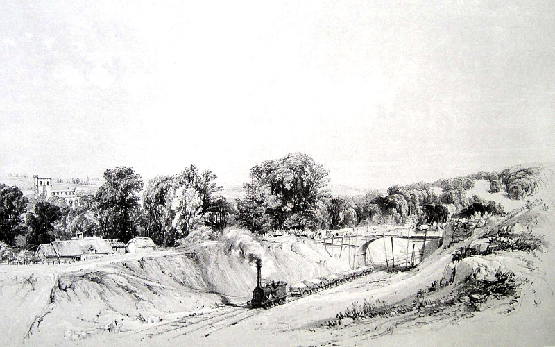
The Harvey Combe on
construction work near Berkhamsted, June 1837, by John Cooke Bourne.
The diminutive locomotive pictured above is a Stephenson Patentee,
the Harvey Combe. One might wonder why an express passenger
locomotive ― “the best of its day”,
to use one commentator’s description [15]
― was relegated to the task of hauling a train of earth
wagons on a construction site. However, before looking into the background of the Harvey Combe,
it is first next necessary to turn to Edward Bury, whose star shone brightly in the
railway firmament for some twenty years and who, together with his
works foreman, James Kennedy, had an important influence on
locomotive development.
|
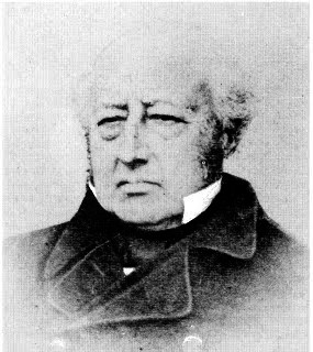 |
|
Edward Bury F.R.S.,
M.I.C.E. (1794-1858) |
Bury was a talented man with a mechanical
aptitude. [16] In 1826 he set up the Clarence Foundry, an engineering and iron foundry
business in Liverpool, where for a number of years
railway locomotives were manufactured successfully for both
domestic and overseas markets:
|
“The first locomotive ever used in the
United Stales is still in good running order on the Little Schuykill
railroad. It was built in Liverpool, England, by Edward Bury. At
that time it was necessary to send a man from England to put the
engine in running order on the road. It was but twenty years ago
that Edward Bury’s engine was placed upon this road. Since then, the
iron track has extended throughout our land; the fierce breathing of
the iron horse is heard in almost every valley; the ingenuity of our
own Mechanics enables them to supply our own engines; and even
furnish them to nations across the ocean.”
Railway Locomotives and Cars,
Volume 24 (1851). |
Bury’s foreman, James Kennedy, [17] had
previously held the position of Manager at the Newcastle factory of
Robert Stephenson & Co. The extent to which Bury and Kennedy
collaborated on their locomotive designs remains a matter of
conjecture, but the prevailing view is that Kennedy was the
principal designer:
“The first engine made by Mr. Bury was the
‘Dreadnought,’ which was started on the Liverpool and
Manchester railway March 12, 1830. She had six wheels and was much
objected to on that account. The next was the ‘Liverpool’;
this was the original engine made by him with horizontal cylinders
and cranked axles. She was placed on the Liverpool and Manchester
Railway on July 22, 1830, and had an 18 inch stroke, two pair of
six-feet coupled wheels, and 12inch cylinders.”
A Practical Treatise on
Railways, Peter Lecount (1839).
The history of Bury’s first two locomotives, the
Dreadnought and the
Liverpool, is confused, both with regard to their construction
and later life. The Dreadnought was intended to compete in the Rainhill
Trials but was not ready in time. No image of the locomotive is
known to exist, but in the biographic sketch she wrote of her husband,
Priscilla Bury describes it thus:
“Mr. Bury’s first locomotive was the
‘Dreadnought’, commenced in 1828. She had the old type of boiler
[return flue?] and six wheels, with
cylinders ten inches diameter, two feet stroke, and two valves ―
one the ordinary, the other the expansion valve ― to allow the
steam to be worked expansively.”
Recollection of Edward Bury, by
his Widow (published privately, Windermere, 1860).
The expansion valve that Priscilla refers to must have made the
Dreadnought one of the earliest ― if not the earliest ―
locomotive to have an adjustable cut-off. Subsequently, the Dreadnought
worked as a ballast engine on the Liverpool and Manchester Railway,
which was then under construction, but it was not retained by the
Company on account of its excessive weight and, some authors
suggest, its rolling motion. The engine was then sold to the Bolton and Leigh
Railway. That is one account of the Dreadnought’s
later life, but there is another ― see fn 18.
A cranked axle.
According to Edward Woods, [19] onetime Locomotive Superintendent of the
Liverpool and Manchester Railway, Bury’s second engine, the
Liverpool, was equipped with a modified form of return-flue
boiler (which accords with Priscilla’s
description of it) that would have left the fireman and driver
facing each other from opposite
ends of the boiler.
Following a serious derailment while at work on the Bolton and Leigh
Railway, the locomotive was rebuilt by Bury with a new
multi-tube boiler, and presumably then appeared as shown below. In this
form it had several similarities to Stephenson’s
Planet. Both locomotives had multi-tube boilers and (nearly)
horizontal cylinders placed between the frames driving a cranked
rear axle. Stephenson was adamant in later years that in arriving at
this arrangement in the Planet he was not influenced by the
Liverpool’s design; [20] the
appearance of these significant design changes in both locomotives contemporaneously must
therefore have been coincidence.
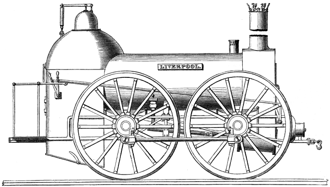
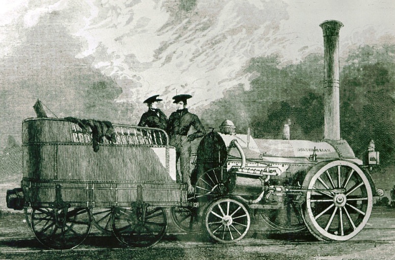
The Liverpool, by Edward
Bury & Co., 1830.
“The first permanent type of modern
locomotive was that of Mr. Edward Bury of Liverpool. Mr. Kennedy, by
whom this locomotive was designed and constructed, had several years
before been the manager of Mr. Stephenson’s works at Newcastle, and
had subsequently joined Mr. Bury, by whom the manufacture of
locomotives was then begun. The locomotive ‘Liverpool’
embodying his improvements, was put to work on the Liverpool and
Manchester Railway on the 22nd of July 1830 . . . . The cylinders are placed in a horizontal position, and the
connecting rods operate upon cranked axles. The framing is that
known as inside framing, and the general arrangements are such as
Messrs. Bury, Curtis, and Kennedy subsequently persisted in with so
much success.”
A treatise on the steam-engine in
its various applications; Artizan Club (1868).
Other than their similarities, there were some significant
difference between the Liverpool and the
Planet.
The Liverpool’s 0-4-0 wheel arrangement
(compared to the Planet’s 2-2-0) was a superficial difference,
but its 6 feet diameter wheels (compared
to the Planet’s 5 feet) were not; this caused George
Stephenson, for no clear reason, to advise the Company not to buy
the locomotive. It is possible that he believed that on the poor
quality track of the time, derailment was more likely with large
diameter wheels, but he might equally have wished to steal a lead
over a competitor.
Bury’s locomotive was equipped with what became known
as a Haycock or Gothic Arch boiler of his
devising. It had a prominent upright firebox, the outer
shell
of which comprised a vertical cylinder capped with a dome, which dispensed with the need for a separate steam dome.
Seen in plan, the inner firebox was D-shaped; although short, it
was deep, giving plenty of space for the fuel to burn through
before the hot combustion gases entered the firetubes.
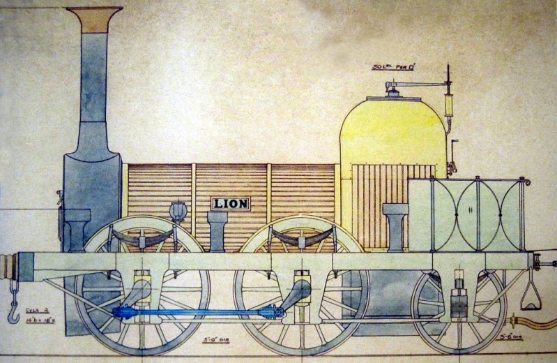
Above and below: a locomotive fitted with a Haycock or
Gothic Arch boiler.
Lion was built in 1838 by
Todd, Kitson and Laird of Leeds for the Liverpool & Manchester
Railway.
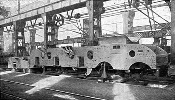
But the most notable difference between the two types of locomotive
lay in their frames (comparable in function to a road vehicle’s
chassis). The Planet was built on an outside ‘plate
frame’; in essence, this was a box structure built out of
vertical planks and/or metal plates (see photograph),
and frames of this type
later became common in locomotives of European manufacture. By
comparison, the Liverpool was built on a frame comprising
iron bars. Perhaps as a result of the popularity of the locomotives
that Bury exported
to North America, the ‘bar frame’ later became standard for locomotives
manufactured there.
4-wheeled locomotives that had twin inside cylinders, a haycock
boiler and bar frames became known as ‘Bury types’.
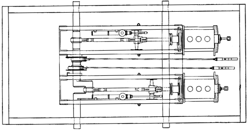
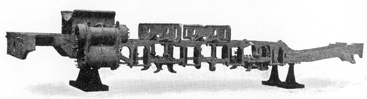
Plan of the Planet’s frame
― cranked rear axle on the left, inside (horizontal) cylinders on
the right.
The cranked axle is supported by 6
bearings, 2 on the main frame and 4 on the sub-frames.
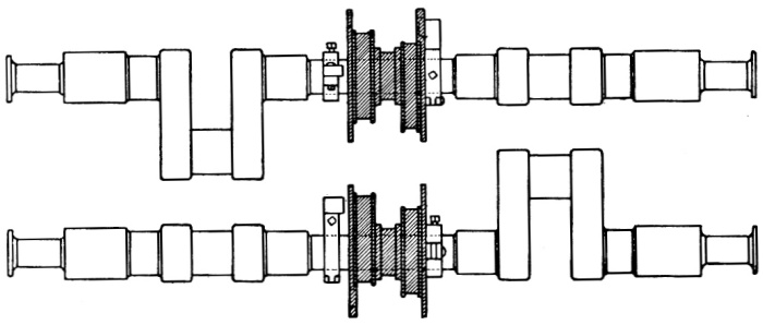
|
 |
|
Top, plate frame for a
4-2-6 locomotive; bottom, bar frame for a 2-6-0. |
|
 |
The Rainhill Trials having demonstrated the feasibility of working
the line with locomotives, the Company bought a number of the Rocket and
(later) Planet types from Robert Stephenson and
Co.; indeed, during the first three years of the Railway’s operation
the firm supplied almost all its locomotive stock. [21] George Stephenson, who by then was generally regarded as a guru on
railway matters,
considered it his prerogative as Chief Engineer to
specify the line’s motive power requirement. Thus, it is hardly
surprising that manufacturers competing with the
family firm would find difficulty
meeting the Railway’s requirement in
circumstances where their product differed substantially ― as, for
instance, did Edward Bury’s bar frame and haycock boiler
construction ― from that
specified by Stephenson, which could, of course, be met easily by Robert Stephenson and Co. And although
Stephenson’s specification might be
met by other manufacturers, royalty payments would become due on
aspects of the design for which Robert Stephenson & Co. held the
patent. It is therefore unsurprising that some board members
came to believe that having their Chief Engineer specify how the
Railway’s motive
power requirement was to be met smacked of nepotism, if not
monopoly.
A entirely new development then arose of a type that has resounding echoes
in our own age. Charles Tayleur &
Co., an engineering firm [22] based near the Railway at Newton-le-Willows
and in which the Stephensons
had a financial interest, proposed what today would be described as
a service management contract. Under its terms, Tayleur & Co. offered to supply, operate
and maintain the Railway’s motive power needs for an agreed sum. Although
the proposal was declined, this type of contract was to appear on the London and Birmingham Railway,
and with interesting consequences.
After much debate [23] and wavering strategy, the
Liverpool and Manchester directors decided that their motive power requirements would
best be met
by open tender. In 1834, Robert Stephenson & Co. delivered the Patentee, the first
ever 2-2-2, which turned out to be the last order that the Liverpool
and Manchester Railway
placed with the firm. Charles Tayleur &
Co. continued to supply the Railway with locomotives until 1837, but
by then the Stephensons had been obliged to severe their connections
with Tayleur due to a conflict of interest issues arising with other
projects in which they were involved, one such being the London and
Birmingham Railway.
While the motive power debate progressed at Liverpool, similar
concerns were fermenting in the boardrooms of the London and
Birmingham Railway, some of whose directors had interests
in both companies. By now construction of the London and
Birmingham line had begun, and the Board’s thoughts were turning to the question
of how motive power was to be sourced. Robert Stephenson drew
up a specification for its locomotives that
conformed with his 2-2-2 Patentee design, which meant either
the Stephensons benefitting directly if they built the engines, or
indirectly (through royalties on the patents)
if they were sourced elsewhere.
|
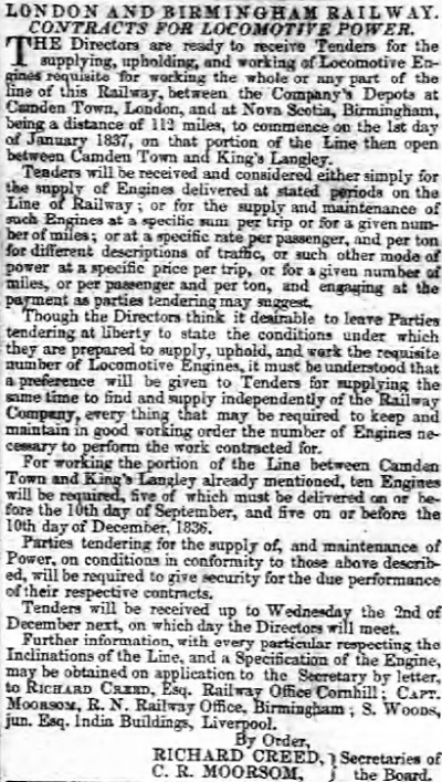 |
|
Birmingham
Gazette, 9th November 1835. |
Towards the end of 1835, the London and Birmingham Railway advertised
for tenders to provide motive power, either by selling the Company
the locomotives or by providing the motive power on a service
management basis. Charles Tayleur & Co. submitted a service
management proposal from which, had it been accepted, the
Company’s Chief Engineer (Robert Stephenson) would have benefitted one way or the other.
However, Tayleur’s
proposal was rejected, possibly for that reason. Edward Bury
also submitted a tender by which the Company would buy locomotives
built to his specification, which he would then operate and maintain
for an agreed rate.
While Bury’s proposal was being considered, Robert Stephenson
attempted to influence the Company’s locomotive policy by having W.
& L. Cubitt, the building contractor for the Berkhamsted section of
the line,
accept a Patentee as a works engine. The locomotive,
originally destined for Belgium, was shipped to London, then up the Grand
Junction Canal to Bourne End where it was assembled and later
depicted at work in Cooke Bourne’s famous drawing.
But Stephenson’s tactic was to no avail and Bury’s tender was
duly accepted:
“The Directors have entered into a
contract, under the guarantee of two responsible sureties, with Mr.
Edward Bury, of Liverpool, an able and experienced builder of
locomotive engines, for the conveyance of passengers and goods, on
the railway, by locomotive power, to whatever extent may be
required, at a fixed rate of remuneration; the Company providing
engines of Mr. Bury’s specification, and Mr. Bury on his part
maintaining and keeping them in repair; the contract to be in force
for three years from the opening of the railway. The Directors have
also contracted for such locomotive engines as will be first wanted,
and for a portion of the carriages.”
The Railway Magazine,
Vol. 1 (1836).
The contract terms were ¼d per mile per passenger,
at a speed not to exceed 22½ mph, and ½d per ton per mile for the
conveyance of goods. [24] The contract was to
remain in force for three years following the opening of the
Railway, but an interim arrangement must have been agreed to cover
the period during which the line was being opened in stages. However, the arrangement proved unworkable.
In July 1839, the contract was annulled and Bury
was appointed Superintendant of the Locomotive Department, for which
he received a
salary. He chose Wolverton in Buckinghamshire, midpoint
on the 112½ mile-long line, as the
location of his headquarters and locomotive workshops, which opened in 1838 and eventually grew into Wolverton Works.
Because Bury was unable to meet the Company’s delivery deadline, the first tranche of locomotives
were built
by a consortium of suppliers working to a common specification (Appendix
III.): indeed, Bury can be said to have been the first
“Chief Mechanical Engineer”
― a later designation, but one applicable nevertheless ― to insist
on standardization:
“It is to be noted, that although the
London and Birmingham engines are made by different persons, they
are constructed exactly alike, in all their parts, and to an exact
size every where, being entirely made from working drawings given
out by Mr. Bury of Liverpool, who contracts to work the line. This
will, eventually, conduce to great economy, as every individual part
of an old and disabled engine, which is worth preserving, can be
used in the formation of a new one.”
The History of the Railway
Connecting London and Birmingham, Lieut.
Peter Lecount R.N. (1839).
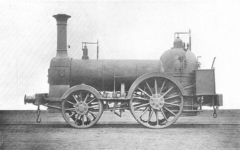
Above, a Bury 2-2-0 passenger locomotive of the London &
Birmingham Railway.
Note the upright cylindrical domed firebox.
Below, a Bury 0-4-0 freight locomotive, built in 1846 by Bury,
Curtis & Kennedy of Liverpool
for the Furness Railway.
All Bury’s locomotives for the London and Birmingham Railway (both passenger and goods) were 4-wheeled (see also
Appendix IV.), the advantages of which Bury set out thus:
“The four-wheeled engine is less costly
than that on six wheels; it can be got into less space; is much
lighter, and therefore, requires less power to take it up the
inclines, and consequently leaves more available power to take up
the train; is safer, as it adapts itself better to the rails, not
being so likely to run off the lines at curves or crossings; is more
economical in the working, there being fewer parts in motion, and
less friction; those parts of the machinery which are common to both
plans are more easily got at in the four wheeled engine the
buildings and turntables are not required to be on so large a scale
as there are fewer parts in the four-wheeled engine; fewer tools, as
lathes, drills, &c., are required; having fewer parts to be
deranged, stoppages are not so likely to take place on the journey.”
A Rudimentary Treatise on the
Locomotive Engine in all its Phases:
George Drysdale Dempsey
(1856).
While Bury might, at first, have had a point on safety ― for he
mentions derailments on curves and crossings ― as the standard of
track improved, so those particular risks diminished. In other
respects his belief that locomotive size had reached the point at
which the law of diminishing returns set in ― that larger engines
delivered less value in relation to their overall cost ― was flawed:
“The locomotives on the London and
Birmingham were small and light compared with those now in use. A
few used in the goods department were coupled. The passenger-trains
were run by an engine on four wheels, the driving-wheel being about
five feet six in diameter. They were swift, but hardly strong enough
for the work, and many of the trains required two engines to draw
them, and a pilot engine was always on the station at Wolverton
ready to go in search of belated trains, and assist them.”
Railways in 1840 . . . . from
Notes of my Life, H. Stowell Brown (1888).
In his History of the Railway connecting London with Birmingham
(1839), Peter Lecount lists the following locomotives as being
active on the line in August 1838:
Lecount also refers to a Stephenson locomotive, but without
identifying it ― if not the Harvey Combe it was probably of
that type, and if so, the data that he provides gives some clue as
to its tractive power:
“A very superior engine was also made by
Robert Stephenson, for carrying the trains up the inclined plane
from the Euston Square station to Camden Town, till the fixed
engines were completed; and the performance of the whole has been
most satisfactory, as may be judged from the following instances.
The average of fourteen trips, of twenty-three miles, up 1 in 440,
with the engine No. 16, was twenty-two miles an hour, with a gross
weight, including the tender, of seventy-five tons, ― viz., fourteen
carriages and one hundred and forty-eight passengers: the
consumption of coke was 148 lbs.
The average of fourteen trips, of three-quarters of a mile, up 1 in
90, from Euston Square to Camden Town, with the large engine built
by Robert Stephenson and Co., was fifteen miles and hour, with
seventy tons, ― viz., fourteen carriages and one hundred and
forty-eight passengers.”
The History of the Railway
Connecting London and Birmingham, Lieut.
Peter Lecount R.N. (1839).
By 1845, the Railway’s locomotive stock consisted of one six-wheeled
(the Harvey Combe?) and 89 four-wheeled locomotives, but by then experience had demonstrated that for high speeds,
heavy loads and severe gradients, larger engines were necessary to
handle the traffic effectively. By the time Bury’s superintendence
of the motive power department ended, the six-wheeled locomotive
had been adopted on the London and
Birmingham Railway, as it had long been on most others;
“ACCELERATION
OF THE MAIL TO LIVERPOOL:
We learn that a desire has been expressed by the Post Office
authorities that the London and North-Western Company should run a
mail train between London and Liverpool (210 miles) in five hours,
and we believe there is little doubt that such an acceleration of
the mail will soon take place. On Friday afternoon the London and
Birmingham directors, who, we believe, had to attend, at Manchester,
a board meeting of the London and North-Western Company ― of which
it will be recollected, the London and Birmingham is now a component
portion ― tested the capacity of the ordinary passenger engines for
such a rapid journey north. The train (a special one) consisting of
six first class carriages left Euston-square at five minutes before
five o’clock in the afternoon, and reached Birmingham at 33 minutes
past seven o’clock, having been detained at Wolverton 14 minutes
beyond the time necessary for the change of engine . . . . It is
necessary to state that the journey over the London and Birmingham
line was made with the ordinary four-wheel passenger engines, with
five feet nine driving wheels. They are Mr. Bury’s make, and weigh,
we believe, between 10 and 11 tons only. Within the last fortnight
two very powerful six-wheel engines, with six feet driving wheels,
and made by the same manufacturer, have been put on the London and
Birmingham line. They are stated to be equal to twelve carriages, at
an average speed of 50 miles an hour over the unfavourable
gradients from Euston to Tring.”
The Standard, 15th September
1846.
In the design of his 4-wheeld locomotives
Edward Bury erred on the side of caution and reliability. But with that caveat, during his time in office
he delivered what was expected of him (see also
Appendix V.):
|
“The Directors considering it of more
importance that passengers should be able to rely on a certain and
safe conveyance to and from the stations where the trains stop, than
that they should in the first instance travel at the highest
attainable speed, have made it their chief aim in the regulation of
the trains to ensure a uniform precision of movement on the railway. In this endeavour they have been ably seconded by their contractor
for locomotive power, Mr. Bury, and a degree of punctuality in the
arrivals and departures has for some time past been attained at all
the stations, which, considering the unavoidable imperfections of a
road so recently formed, and the many difficulties to be surmounted
in every new undertaking, the Directors could scarcely have
anticipated, and which they may add has not been accomplished upon
any other railway.”
Herapath's Railway Journal,
Vol. 4 (1838). |
From 1845 Bury began to build larger six-wheeled locomotives with
his usual bar frames; one of these, a 2-2-2 passenger locomotive of
1847 was preserved and is on display at Cork railway station.
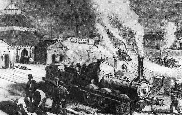
This sketch is of a scene outside
the Luggage Engine House at Camden (‘The Roundhouse’).
The unidentified 6-wheeled
freight locomotive in the foreground appears to be a Bury design.
In March, 1847, Bury resigned his post from what by then had become
the London and North Western Railway Company; he later became, for a
short time, General
Manager of the Great Northern Railway after which he retired from
railway business. His entry in the Oxford Dictionary of
National Biography concludes thus:
“By his
engineering capabilities, his mechanical knowledge, his good
judgement, and his tact, he won the complete confidence of the
directors and of those who were employed under him.”
CHAPTER
13
――――♦――――
APPENDIX I.
PRESS REPORTS ON THE RAINHILL TRIALS.
LOCOMOTIVE CARRIAGES.
The Morning Post, 9th
October 1829.
In the month of April last the Directors of the Liverpool and
Manchester rail-roads offered a prize of £500 for the best
locomotive engine, and the trial of the carriages which had been
constructed in consequence took place at Liverpool on Tuesday. The
running ground was on the Manchester side of the Rainhill-bridge at
a place called Kenrick’s Cross, about nine miles from Liverpool. At
this place the rail-road runs on a dead level, and formed a fine
spot for trying the comparative speeds of the carriages. For the
accommodation of the ladies a booth was erected on the south side of
the rail-road, equidistant from the extremities of the trial ground. Here a band of music was stationed, and amused the company during
the day. The Directors, each of whom wore a white riband in his
button-hole, arrived on the course shortly after ten o’clock in the
forenoon, having come from Huyton on cars drawn by Mr. R.
Stephenson’s locomotive steam carriage, which moved up the inclined
plane from thence with considerable velocity. Meanwhile Ladies and
Gentlemen, in great numbers, arrived from Liverpool and Warrington,
St. Helen’s and Manchester, as well as from the surrounding country.
The pedestrians were extremely numerous. The spectators lined both
sides of the road for the distance of a mile and a half. It is
difficult to form an estimate of the number of individuals who had
congregated to behold the experiment; but there could not, at a
moderate calculation, be less than 10,000. Some Gentlemen even went
so far as to compute then at 15,000.
Never, perhaps, on any previous occasion, were so many scientific
gentlemen and practical engineers collected together on one spot as
there were on the rail-road. The interesting and important nature of
the experiments to be tried had drawn them from all parts of the
kingdom.
Mr. Burstall, of Edinburgh, did not bring his carriage out, in
consequence of its having met with an accident on its road from
Liverpool to the Course. The locomotive carriages ran up and down
the road during the forenoon, more for amusement than for
experiment, and even startling the unscientific by the amazing
velocity with which they moved along the rails. Mr. Robert
Stephenson’s carriage attracted the most attention during the early
part of the afternoon. It ran without any weight attached to it, at
the rate of twenty-four miles in the hour, emitting very little
smoke, but dropping its red-hot cinders as it proceeded. Cars
containing stones were then attached to it, weighing, together with
its own weight, upwards of 17 tons, preparatory to the trial of its
speed being made. This trial occupied, with stoppages, 71 minutes,
and proved that the carriage can, drawing three times its own
weight, run at the rate of more than ten miles in the hour.
Mr. Hackworth, of Darlington, ran his carriage along the course
during the day, but no trial of its speed with weights took place.
Mr. Winan’s machine, worked by two men, and carrying six passengers,
was also on the ground. It moved with no great velocity, compared
with the locomotive steam carriages, but with considerable speed
considering it was put in motion by human power. Mr. Brandreth, of
Liverpool, has his locomotive carriage on the road. It was worked by
two horses, on the principle of the tread-wheel. Though its velocity
was not more than four miles per hour on this occasion, it is a
carriage which will be useful for a variety of purposes on the
rail-road.
But the speed of all the other locomotive steam-carriages on the
course was far exceeded by that of Messrs. Braithwaite and Co.’s
beautiful engine from London. It shot along the line at the amazing
rate of thirty miles in the hour.
The contests were to continue for two or three days.
――――――――
WEDNESDAY ― SECOND DAY.
The Standard, 12th
October 1829.
The course was far from being so crowded today as it was yesterday. The company was more select, however, consisting chiefly of
gentlemen and men of science. Persons who visited the ground for
purpose of amusement did not experience the same degree of
gratification which those experienced who visited it on the
preceding day, in consequence of all the machines which exercised
yesterday not having exercised today. Still the experiments, though
limited, were highly interesting to scientific men.
Messrs. Braithwaite and Ericson’s engine (the Novelty) proved itself
today to be as good (proportionately) at drawing a load as running
without one. It drew in one hour, three times its weight, a distance
of 20¾ miles! The carriages of Messrs. Stephenson, Hackworth, and Brandreth were also on the course this day, and took several trips,
but were merely by way of exercise. One of the horses engaged in
working Mr. Brandreth’s carriage fell, we understand, through the
floor but was extricated without much injury. The weather became
wet, and the rail-ways clogged with mud, which made it necessary to
suspend the prosecution of the experiments before the day had half
elapsed. The attendance of spectators this morning was by no means
so numerous as on the preceding day, but there were few of those
absent ― the engineers, men of science, etc. ― whose presence was
most wanted. The Earl of Derby paid the rail-way a visit in the
course of the morning, and seemed to take great interest in the
proceedings.
THURSDAY ― THIRD DAY.
Mr. Stephenson’s engine, “The Rocket,” weighing 4 tons 3 cwt.,
performed, today, the work required by the original conditions. The
following is a correct account of the performance:―
The engine, with its complement of water, weighed 4 tons 5 cwt., and
the load attached to it was 12 tons 15 cwt., which, with a few
persons who rode, made it about 18 tons. The journey was 1½ miles
each way, with an additional length of 220 yards at each end to stop
the engine in, making in one journey 3½ miles. The first experiment
was for 35 miles, which is exactly ten journeys, and, including all
stoppages at the ends, was performed in 3 hours and 10 minutes,
being upwards of 11 miles an hour. After this a fresh supply of
water was taken in, which occupied 16 minutes, when the engine again
started, and ran 35 miles in 2 hours and 52 minutes, which is
upwards of 12 miles an hour, including all stoppages. The speed of
the engine with its load, when in full motion, was from 14 to 17
miles an hour; and had the whole distance been in one continuous
direction, there is no doubt that the result would have been 15
miles an hour. The consumption of coke was very moderate, not
exceeding half a ton in the whole 70 miles. At several parts of the
journey the engine moved at 18 miles an hour.
Mr. Hackworth’s Darlington engine was withdrawn, on account, we
believe, of some part of it falling accidentally out of order. It is
nearly of the same size and weight as Mr. Stephenson’s and like that
engine requires the addition of an engine tender to carry its water
and fuel. Judging from several short trips which it performed on the
rail-road, by way of exercise, we should pronounce it to be a
machine of great power.
FRIDAY ― FOURTH DAY.
Today a public notice appeared, from Messrs Braithwaite and Ericson,
stating that, in consequence of the alterations made in the
conditions of the competition, the definitive trial of the new
engine had, with the approbation of the judges, been deferred until
Saturday at eleven. Friday became thus a dies non in the
competition; the engines of Mr. Stephenson and Messrs. Braithwaite
and Ericson being the only two which, to use the language of the
turf, had been placed by the judges.
SATURDAY ― FIFTH DAY.
In the expectation of witnessing the Novelty perform its appointed
task, the attendance of company on the ground was more numerous
today than it had been on several of the preceding days. Three times
its own weight having been attached to the engine, the machine
commenced its task, and performed it at the rate of 16 miles in an
hour. Mr. Stephenson’s engine, the Rocket, also exhibited today. Its
tender was completely detached from it, and the engine alone shot
along the road at the almost incredible rate of 32 miles in the
hour. So astonishing was the celerity with which the engine, with
its apparatus, darted past the spectators, that it could be compared
to nothing but the rapidity with which the swallow darts through the
air. Their astonishment was complete, every one exclaiming
involuntarily, “The power of steam is unlimited!”
The experiments will be continued during the present week.
――――――――――――
THURSDAY ― EIGHT DAY
The Morning Post, 20th
October 1829.
Liverpool, Oct. 15.― We may consider the trial of Locomotive Engines
virtually at an end. In consequence of the number of petty accidents
which occurred to the London Engine, Messrs Braithwaite and Ericson
(rather unadvisedly we consider) took their engine to pieces after
the performance of Saturday, and they only had the joints of the
boiler-pipe closed this morning. Every engineer knows the effect of
a high pressure upon a green joint; but as the Novelty had
been entered for this day’s contest, the proprietors determined upon
starting. Accordingly, at one o’clock, the engines set off, and
performed about seven miles in a manner highly satisfactory, going
at one time at the rate of 24 miles an hour, with its customary
load, when the green joint of the boiler pipe gave way ― as might
have actually been expected ― and the engine was obliged to stop. It
is much to be regretted that the Novelty had not been built
in time to have the same opportunity of exercising that Mr.
Stephenson’s engine had, or that there is not in London, or its
vicinity, any railway where experiments with it could have been
tried. It will evidently require several weeks to perfect the
working of the machine and the proper fitting of the joints; and
under this impression, Messrs. Braithwaite and Ericson have acted
wisely in withdrawing, as they have done, from the contest.
In the early part of the day Mr. Stephenson’s engine ascended the
Rainhill inclined plane several times with heavy loads of
passengers, and did this at the rate of twelve miles an hour. Now,
considering that the rate of ascent is one in 96, or upwards of a
third of an inch in a yard, we consider the erection of fixed
engines on that and the other inclined plane at Sutton as quite out
of the question, and that before very long, we may hear of railways
by the sides of our turnpike roads.
Mr. Burstall exercised his engine, but we believe we are correct in
stating that this gentleman is conscious that his engine is not
sufficiently powerful to compete with the other three. He will,
however, continue to try its powers.
The course is thus left clear for Mr. Stephenson; and we
congratulate him, with much sincerity, on the probability of his
being about to receive the reward of £500. This is due to him for
the perfection to which he brought the old-fashioned locomotive
engine; but the grand prize of public opinion is the one which has
been gained by Messrs. Braithwaite and Ericson, for their decided
improvement in the arrangement, the safety, the simplicity, and the
smoothness and steadiness of a locomotive engine; and however
imperfect the present work of the machine may be, it is beyond a
doubt ― and we believe we speak the opinion of nine-tenths of the
engineers and scientific men now in Liverpool ― that it is the
principle and arrangement of this London engine that will be
followed in the construction of all future locomotives. The powerful
introduction of a blast bellows, the position of the water-tank
below the furnaces of the carriage, by which means the centre of
gravity is brought below the line of central motion, the beautiful
mechanism of the connecting movement of the wheels, the absolute
absence of all smoke, noise, vibration, or unpleasant feeling, of
any kind, the elegance of the machinery ― in short, the tout
ensemble ― proclaim the perfection of the principle; and we deeply
regret that the want of sufficient time to practice the mere
mechanical motion of the engine has caused Messrs. Braithwaite and
Ericson to withdraw ― their motive for which we hope will be duly
appreciated by the public and by the Railway Directors, inasmuch as
we believe it has been only to devote their whole time and talent to
the perfection of their machine.
In awarding the principal prize, we cannot doubt both the
inclination and the intention of the Directors to purchase the
engines which have been exhibited, and to reward with minor prizes,
the unsuccessful but ingenious competitors.
――――――――――――
THE RAILWAY CONTEST.
The Standard, 29th
October 1829.
On Tuesday last, the judges appointed to report on the performances
of the locomotive carriages at Rainhill, gave in their report to the
directors, and in consequence of the opinion expressed by them, the
prize of £500 was adjudged by the directors to Mr. Robert Stephenson
of Newcastle. It has not yet been decided whether the report of the
judges shall be published or not. We understand, however, that it
expresses no opinion as to the principle of Messrs. Braithwaite and
Ericson’s carriage, but merely gives a statement of the respective
performances of the different carriages.
――――♦――――
APPENDIX II.
THE ROCKET LOCOMOTIVE, 1829.
from
Hand books of the Science Museum:
LAND TRANSPORT.
Pub. H.M.S.O. 1931.
This celebrated engine was constructed by Messrs. R. Stephenson &
Co. in 1829, to compete for the £500 prize offered by the directors
of the Liverpool and Manchester Railway to the makers of the most
successful locomotive competing at a trial to be held at Rainhill in
October of that year.
The “Rocket” left Newcastle on September 12th, 1829, going part of
the way by canal, and was delivered by wagon at Rainhill on October
2nd; the competition commenced on October 6th and continued for
eight days. At that time the “Rocket" was painted yellow, relieved
with black, while the chimney was white. Her greatest speed was 29
miles an hour; some years afterwards, however, she ran 4 miles in
4½ minutes, or at the rate of 53 miles an hour. After the trial the
“Rocket” was purchased by the Liverpool and Manchester Railway Co.,
and worked on the cutting between Chat Moss and Salford till the
opening of the line on September 15th, 1830; during this period,
however, the engine was improved by the addition of a smokebox and
the chimney was shortened. At the ceremony of opening the railway,
this engine ran over and fatally injured the Right Hon. William Huskisson, then M.P. for Liverpool; this sad accident, however, drew
great attention to the possibilities of travelling by steam, as
George Stephenson took the injured gentleman to his destination, 11
miles away, at a speed of 36 miles an hour. The “Rocket” worked on
the Liverpool and Manchester line till 1836, when it was removed to
the Midgeholme Railway, near Carlisle, where it ceased running in
1844; it was brought to South Kensington in 1862.
The engine as it now exists differs in several respects from its
form in 1829; the cylinders were originally arranged at an
inclination of 35 deg. with the horizontal, but they were altered in
1831 to their present inclination of 8 deg.; the present trailing
wheels are quite modern, but the original wheels, which were also of
cast iron, were 30 inches diameter. The firebox originally had a double
copper wrapper plate forming a water-jacketed top and sides, but the
front and back were dry plates. The latter were soon lined with
firebrick, and finally, before the cylinders were lowered, the
present iron water-jacketed back was fitted.
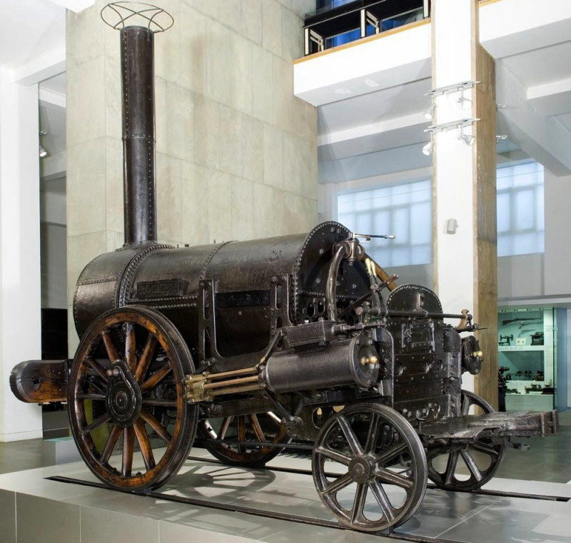
Rocket,
as rebuilt, was similar in appearance to
Northumbrian. The
firebox has been stripped down to expose the firetube ends.
Note the absence of brakes.
――――――――
This model, which is partly in section, represents the famous
locomotive “Rocket” as originally built for the Rainhill trials in
1829.
The engine ran on four wheels and had two cylinders, 8 in. diameter
by 17 in. stroke, placed at the rear end of the boiler and inclined
downwards at 35 deg. with the horizontal; the piston rods drove the
front wheels, which were 56.5 in. diameter, thus giving a tractive
factor of 19.4. The trailing wheels were 30 in. diameter and the
wheel base 7.17 ft. The cylinders were mounted on iron plates, which
were bolted to the boiler shell and supported by stays; these plates
also carried the guide bars, which were of square section, set
diagonally, while the crossheads were of brass, in halves, bolted
together and embracing the bars. The steam chests were below the
cylinders and the slide valves were driven, through an intermediate
shaft and levers, by a pair of eccentrics fixed to a loose sleeve
which could be moved endwise along the shaft by a pedal so as to
engage with either of two drivers, one set for forward and the other
for backward running. The valve rods had gab ends, so that the
valves could be disengaged and worked by hand levers when reversing. The crankpins had spherical ends, to allow for irregular motion of
the engine relative to the driving axle.
The boiler was a cylindrical shell, 40 in. diameter by 6 ft. long,
made in two rings, with a circumferential lap joint and longitudinal
butt joints; the flat ends were secured by angle rings and tied
together by longitudinal stays.
The shell was traversed by twenty-five copper tubes, 3 in. diameter,
secured in holes through the end-plates. The firebox had a double
copper wrapper plate forming a water-jacketed top and sides, but the
front and back were dry plates. Copper pipes connected the water and
steam spaces of the firebox with those of the barrel. The total
heating surface of the boiler was 138 sq. ft., that of the firebox
being 20 sq. ft.; the grate area was 6 sq. ft. The chimney was
nearly 15 ft. high, above the rails, and was swelled out at the
base to cover the tube ends; it was supported by stays from the
cylinder plates.
Steam from the boiler was admitted to the cylinders by two pipes
leading from a regulating cock fixed above the firebox and which
received steam from a dome through an internal pipe. The boiler
pressure was limited to 50 lb. per sq. in. by two safety valves, one
of which was loaded by a weight and lever, while the other was a
lock-up spring loaded valve covered by a small dome. A mercurial
gauge was fitted beside the chimney and was arranged to indicate the
steam pressure from 45 to 60 lb.; a water gauge was fitted behind
one of the cylinders and two gauge cocks near the front end of the
boiler. The feed water was introduced by a long-stroke feed pump
worked from one crosshead, while the exhaust steam was passed into
the chimney by two pipes, each fitted with a brass nozzle 1.5 in.
diameter.
The framing of the engine was wholly between the wheels, and was
built up of 4 in. by 1 in. flat bar iron bent down at the rear end
to accommodate the firebox and rear axle; to this the cast-iron axlebox guides were secured, and four brackets to support the
boiler. The weight was transmitted to the axles by plate springs.
The driving wheels were constructed with cast-iron bosses, in which
the crankpins were fixed, oaken spokes and felloes, and iron tyres
secured by bolts. The engine weighed 3.25 tons when empty and 4.25
tons in working order.
The tender was a four-wheeled wooden truck carrying the fuel in the
body and the water in a large barrel above it. The axles had outside
bearings and plate springs, the wheels were 36 in. diameter, and the
wheel base was 4 ft. It weighed 3.2 tons when loaded, so that the
total weight of engine and tender in working order was 7.45 tons.
――――♦――――
APPENDIX III.
A DESCRIPTION OF BURY’S LOCOMOTIVES AS USED ON THE
LONDON
AND BIRMINGHAM RAILWAY
from
A Practical Treatise on Railways, Explaining
their Construction and Management
(pp 201-206)
by
Lieut. Peter LeCount R.N., F.R.A.S., C.E. (1839)
The following are the engines in use on the London and Birmingham
Railway and which were made by Mr. Bury of Liverpool. The
description here given applies to both the passenger and goods’
engines, except when otherwise stated.
The two cylinders are to have an 18-inch stroke, those of the
passenger engines being 12 inches, and the goods engines 13 inches
in diameter, with single slide valves, brass spring pistons, and
cast iron packing; the cover of each cylinder having one oil cup.
The boilers are made of the best Yorkshire plates, either Bowling or Lowmoor. The fire-boxes are of the same material, and are welded so
as not to have the rivets or lap exposed immediately to the action
of the fire. They are ⅜ths of an inch thick, the back plates half an
inch, the outside of the fire-box and the backplate ⅜ths of an inch,
and the rest of the boiler 5/16ths of an inch. Full-sized drawings
are furnished to shew how the plates are to be worked; the plate for
the tubes at the smoke-box end is half an inch thick, and a lead
plug, ⅝ths of an inch in diameter, is riveted in the crown of the
fire-box.
The tubes are two inches in diameter inside, and are secured with
steel hoops at the fire-box end, and iron hoops at the chimney end. These hoops are made to a given gauge; and the tubes are of the best
rolled brass, No. 14 wire gauge thick; the arrangement as well as
the exact size of the tubes being regulated by a template.
The engines have four wheels; those for the passengers are 5½ and 4
feet in diameter, and those for the goods are each pair 5 feet in
diameter. Each wheel has a cast iron centre; and the spokes are of
wrought iron, accurately fitted into the nave. The tire consists of
two thicknesses, the inner being ¾ths of an inch when finished, of
the best Staffordshire iron, well secured to the end of the spokes
by riveting, the ends of the spokes having been previously turned in
their exact position. The outside tire is made of the very best
Bowling or Lowmoor iron 1⅝ths inches thick when finished. When the
outside of the inner tire has been well riveted to the spokes it is
turned; and the inside of the outer tire having been accurately
bored, so as to secure a perfect fit, it is then shrunk on, and the
outside turned and finished. The naves are bored out, and the axles
turned to fit; they are secured on by two steel keys, one inch
square, at right angles with each other. The goods’ engine wheels
are connected on the outside by a rod, with a ball pin at one end,
and a parallel pin at the other. These engines have also a damper to
their blast pipe.
The crank axles are made from Backbarrow iron, cut out of solid
blocks, and finished according to full-sized drawings. The straight
axles are made of the very best scrap iron. The framing of the
engine is of wrought iron accurately fitted. There is one pump
attached to each cross-head and made of good tough brass, the
suction pieces being connected by Macintosh hose pipes, with screw
coupling joints next the engine. The eccentrics are fixed on the
crank axles in the mode shewn by drawings. The steam and exhausting
pipes are of copper, No. 12 wire gauge in thickness. When these
engines are made by other persons, templates and full-sized working
drawings are given out, from which no deviation whatever is allowed
without Mr. Bury’s approbation, so as to secure all parts of the
engines matching each other.
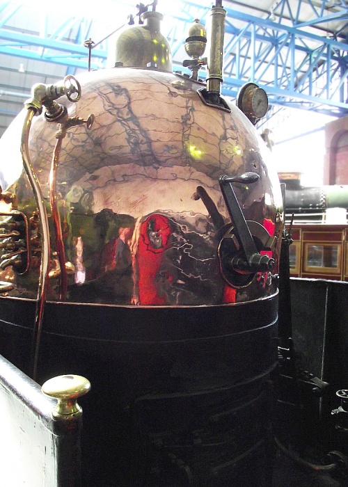
A Bury copper-domed firebox dating
from 1846.
The top of the fire-box has a copper cover, No. 16 wire gauge thick,
secured to the wooden covering on the lower part of the fire-box and
body of the boiler, by screws two inches apart. The wooden covering
on the fire-box is finished to ⅝ths inches thick, and is made fast
to the boiler by two hoops; and round the fire door it is lined with
thin sheet iron under the hoops; the sheets being 6 feet long, and 2
feet 3 inches broad, with a hole cut out for the furnace, and
secured at the ends by screw nails 2 inches apart, to prevent the
fire from burning the wood casing on the boiler. The casing on the
barrel of the boiler is secured by four hoops, with a strip of brass
under the fore-end hoop, about 2½ inches in breadth, to cover the
ends of the lining and the rivet heads at the junction of the barrel
of the boiler, and the smoke-box. The boiler is wrapped in at least
three thicknesses of flannel all over.
The lagging on the boiler is put together with iron feathers ⅝ by ⅛;
by the boiler is covered over the lagging with thin sheet lead,
about 3½ feet broad along the top of the barrel. The smoke-box is
No. 7 wire gauge thick, and the chimney is No. 13 wire gauge. The
cover on the lock-up safety valve is of brass, secured to the
boiler; there is a brass frame round the door of the smoke-box, and
a brass handle to the small door in the middle of the large one.
All the pins of the joints are of steel, and hardened when
practicable, but if not, they are steeled and hardened, and the
working parts of the engine, which are of iron, are case hardened.
In making the boilers, the sharp edges of the rivet holes are taken
off on both sides, and the rivets and rivet heads made to
correspond. The engines are furnished with a wooden guard, and two
leather buffers stuffed with cotton flock; and there are a draw-bar,
draw-pin, and loop in the centre of the wooden guard, to connect
them to the tender. They have three water gauge cocks, and a glass
water gauge, with a lamp stand; also a whistle, and a number plate
on each side of the boiler; and they are furnished with a complete
set of screw keys.
All the screws in all the engines correspond, for which purpose,
either master taps, or sets of stocks and dies, at the option of
other makers, are furnished them by Mr. Bury. They receive two coats
of paint, and are finished with two coats of the best varnish. They
are guaranteed for one month, or 1000 miles, during which trial, no
other work is allowed but the tightening of cotters, and the very
best workmanship and materials that can be produced, are in all
cases rigidly insisted on.
The framing of the tenders is of well-seasoned oak, or ash timber,
thoroughly secured with iron knees and bolts, having an iron box No.
7 wire gauge thick, underneath to carry the coke, which box is
secured to the wooden frame. The tank contains 700 gallons of water. The wheels are of cast-iron, turned to receive a tire of either
Bowling or Lowmoor iron, bored out to secure a perfect fit, and
finished to 1¼ inches thick. The axles are 3¼ inches in thickness,
of the best hammered scrap iron; and the journals are 2¼ inches in
diameter, case-hardened, with brass bushes and oil box.
The steadiment for the axles consists of two plates, one outside,
and the other inside the framing; both of them being bolted through
the framing, and secured together below, by a piece of iron between
the plates for steadying the axle bushes. These are made completely
parallel, and the bushes fitted into these so as to move up and
down, but in no other direction. The tenders have buffers, a spring
to which the load is attached, and also four springs by which they
are supported, one over each oil box.
The tank is No. 10 wire gauge thick, having two brass cocks or
valves, and rod handles with bushes for the top of the rods; also
two copper pipes, 1¾ inches in diameter, for carrying water from the
tender to the engine. The tender frame and tank have two coats of
paint inside and out, and two coats of varnish. They are fitted up
with a brake, and furnished with a complete tool box; a wire sieve
in the main hole of the tank to prevent dirt or water from getting
into the tank; and two Macintosh hose pipes, one to each suction
piece, with the necessary connexion to attach them to the engine.
When water requires to be pumped from the tender into the boiler of
the engine, previous to the starting of the train, it is the usual
practice to run the engine backwards and forwards for a short
distance, in order to work the force pumps. This increases the wear
and tear both of the engine and the road, besides inducing a
liability in a crowded station of running foul of something, if
great care be not taken. The following contrivance will obviate the
necessity of this inconvenient method of filling the boiler. A
square pit should be sunk in some convenient part of the line,
selected with reference to its intended use. This pit should be
large enough to admit a pair of three-feet wheels fixed on an axle
similar to the carriage wheels. There should be no flanges, and a
part of the circumference of these wheels should come up through the
rails, which must be cut so as to admit them, additional chairs
being put in to support the ends of the rails. This part of the
circumference of the wheels thus becomes a part of the railway, the
wheels being made to lock at pleasure; but when the engine requires
to pump water into the boiler, it must be brought with its driving
wheels directly on those in the pit, and these latter being then
unlocked, the steam is let gradually on, and the pumps worked as
long as is found necessary to fill the boiler, without the engine
advancing from the exact spot in which it was first placed, the only
effect produced by the driving wheels of the engine, being to turn
round the wheels fixed in the pit. When the boiler is filled, the
pit wheels are locked, and the engine proceeds to the performance of
her assigned duty. How much more performance assigned duty
advantageous this mode of filling the boiler is, will be readily
seen, particularly when it is remembered that if engine-men are not
looked well after, they will oil the driving wheels and the rails
when in the engine house, and then letting on the steam, fill their
boiler by means of the wheels slipping round on the rails. We have
often seen this carried to such an extent, that streams of sparks
have been struck out by the attrition. When no better plan can be
obtained, the engine should have one end lifted by screw-jacks, till
the driving wheels are off the rails, and the steam may then be let
on without any damage being done.
――――♦――――
APPENDIX IV.
A DESCRIPTION OF BURY’S LOCOMOTIVES AS USED ON THE
LONDON
AND BIRMINGHAM RAILWAY
A Practical Treatise on Railways, Explaining
their Construction and Management
(pp 377-378)
by
Lieut. Peter LeCount R.N., F.R.A.S., C.E. (1839)
Among the leading improvers of these machines, is Mr. Edward Bury of Liverpool, who now contracts
for the locomotive power on the London and Birmingham Railway. The
distinguishing features of his plan are horizontal cylinders: these
were first put outside under the framing, but are now inclosed
within the smoke-box, which all his engines have, except two made
for the Liverpool and Manchester Railway. Inside bearings, and
cranked axles, and horizontal cylinders, however, were before used
by Gurney in his common road engines. Ericson’s engine the Novelty
also had the former. The first engine made by Mr. Bury was the
Dreadnought, which was started on the Liverpool and Manchester
Railway March 12, 1830. She had six wheels, and was much objected to
on that account. The next was the Liverpool: this was the original
engine made by him with horizontal cylinders and cranked axles. She
was placed on the Liverpool and Manchester Railway on July 22, 1830,
and had an 18-inch stroke, two pair of six-feet coupled wheels, and
12-inch cylinders.
The great danger in cranked axles is from their breaking, which,
with four-wheeled engines, might occasion considerable damage. They
have been broken repeatedly, but this has not happened fairly to one
of Mr. Bury’s manufacture; only two have been broken, and in both
cases from bad welding. One of these, the engine No. 14 on the
London and Birmingham Railway, was discovered to have been actually
running for some time with a broken axle, without its being found
out: this arises from the eccentrics being keyed on to the weakest
part of the axle, and thus forming a protection against accidents. The above axle had only two-thirds of its section soundly welded
when sent from the manufactory.
Mr. Bury’s engines are now all made with cranked axles and four
wheels, the goods’ engines being coupled, and the passengers not. We
attribute the success of his axles in some measure to the mode of
constructing the framing, and to his bearings being inside the
wheels, as any shock from obstructions on the road is thus thrown
upon the bearings and not on the crank; the framing is made with
great breadth, and but little depth, in order to resist lateral
shocks; whereas most other makers have great depth, and but little
width, which would afford the most powerful resistance to vertical
shocks, but, in conjunction with the bearings being outside the
wheels, would throw all the lateral ones on the cranks. Many broken
axles, however, have been produced by gross neglect in their
manufacture. We have seen one which had been welded together, and
there was not a junction of a tenth of an inch in the iron, all
round; the whole central part being perfectly black, with not the
smallest sign of welding. Mr. Bury cuts his out of the solid iron,
and only welds the part joining the cranks to set them at right
angles. Some makers twist the axles for this purpose.
――――♦――――
APPENDIX V.
SOME LOCOMOTIVE FACTS AND FIGURES
The Monthly Chronicle of Events, Discoveries, Improvements.
Vol. 1 (1840).
The locomotive department of the London and Birmingham railway has
been conducted, under the care of Mr. Edward Bury, with remarkable
skill, economy, and success. Mr. Bury is an engine builder, and some
of his engines are in use in this country [The U.S.A.]. One
of them on the Boston and Providence, and another on the Boston and
Worcester rail-road, are beautiful and efficient machines. There are
now on the London and Birmingham railway 82 engines of his
construction. According to a report lately published, the number of
miles which have been run by these 82 engines, from September 17th,
1838, the date of the general opening of the line, to August 31st,
1840, is 1,635,396; the average number by each engine 19,944; the
greatest number by any one engine 41,932 miles. The number of miles
run in the six months from December 15, 1839, to June 14, 1840, was
474,154; the greatest number by any one engine was 15,228. During
this period, of nearly two years, three engines only have broken an
axle, two of which were on passenger trains, and one on a
merchandise train.
The number of passenger trains now running daily, is 28, or 14 each
way. The number of journeys during the six months was equal to 3,459
through the whole line of 111 miles, by passenger trains, and 813 by
goods trains, making 4,272 in all, equal to an average of 23 per
day, Sundays included. The journeys on Sundays are fewer than on
other days. The average time of performing the journeys of 111
miles, excluding the stoppages at the stations, was 4 hours 27
minutes, which is equal to an average of 25 miles an hour.
The number of passengers conveyed, from the opening of the line to
the 1st of September last, was 1,239,526; and the aggregate of miles
travelled by them amounted to 80,942,952, equal to 65 miles and 3
tenths for each passenger. No case of death or fractured limb has
occurred from an accident to any passenger. Two passengers were
severely injured, one at the inclined plane between the Euston and
Camden stations, and one at the Coventry station, but in both
instances the parties recovered. The average gross load of the
engine on each passenger journey, carriages included, was 39.98
tons; and of each engine on the goods trains 98.67 tons.
――――♦――――
|
FOOTNOTES. |
|
1. |
JOHN URPATH
RASTRICK F.R.S. (1780-1856): a
distinguished civil engineer, whose career bridges the
gap between Thomas Telford and Robert Stephenson. Early
in his career he worked at the Bridgenorth Foundry, a
business that supplied Richard Trevithick with high
pressure steam engines to Trevithick’s design. He
later became managing partner at the works of Foster and
Rastrick at Stourbridge, a manufacturer of a wide range
of machinery including boilers and steam engines. By the
1820s, Rastrick had become involved in railway projects,
his most famous being the London to Brighton Line. Other
than railways, Rastrick designed a range of machinery
and appeared before parliamentary committees as an
expert witness on railway schemes.
JAMES WALKER F.R.S. F.R.S.E. (1781-1862): unlike
Rastrick, Walker had a general civil engineering
practice, being involved with the construction of roads,
bridges, canals, harbours, docks and lighthouses. His
major railway project was to survey what the Leeds and
Selby Railway, which was opened in 1834. It was Walker
who suggested that a locomotive competition took place
to settle the argument over whether a steam locomotive
was capable of working the Liverpool and Manchester
Railway, with a substantial cash prize going to the
winner. The outcome was the Rainhill Trials, Rastrick
and Walker both being judges. |
|
2. |
The pair commenced with an inspection of the Liverpool and
Manchester Railway, arriving at Manchester on 14th
January, 1829. On the following day, they inspected the
Bolton and Leigh Railway and an unspecified locomotive;
Stephenson, who accompanied them, stated that it
incorporated the best principles he had yet constructed,
so it may have been the Lancashire Witch. On 16th
January they inspected (and were impressed by) Blenkinsop’s locomotive at Leeds. The 17th to 20th
January was spent on the Stockton and Darlington Railway,
where they were able to see various modes of motive
power at work. On the 21st January they visited the Hetton Railway, where they found that Stephenson’s
locomotives had been replaced by cable haulage. The
remainder of the trip was spent in discussions and
collecting data. |
|
3. |
Based on fuel consumption of 2.5 lbs per
ton mile for locomotives, Rastrick and Walker calculated
that a locomotive travelling 30 mile per day for 312 days per year,
with a load of 13 tons, would consume coal to the value
of £111. They stated that 123 engines would be required
to work the estimated traffic, giving an annual fuel
bill £13,653. Making an allowance for
coal consumed in raising steam each day, the fuel bill for
the suggested complement of fixed engines totalled £3,784. |
|
4. |
Despite being over the weight limit for a 4-wheel
locomotive (Rule 5), Sans Pareil was allowed by the judges to take
part in the trials, but not to compete for the prize. There is no
consistent view on whether San Pareil was mounted on springs
at the time of the
trials, as required by Rule 4, but it is unlikely
due to the risk of the up-and-down motion imparted on
the locomotive by its (vertical) reciprocating piston
rods causing the pistons to collide with the cylinder
head. |
|
5. |
Although at first glance the Novelty appeared to
be equipped with a vertical boiler, its boiler was in
fact of composite construction (see main text). Genuine
vertical boilers were used on rail vehicles, such as
cranes, shunting locomotives and steam rail cars,
Sentinel and Clayton being leading exponents of the
latter. Vertical cylinders were also used in some
industrial applications, the American Shay articulated locomotive
being an example. |
|
6. |
Besides protecting their ends from the intense heat of
the furnace, the firebrick arch prevented the combustion
gases travelling directly into the firetubes. The longer
path that they were forced to take to reach the firetubes gave
more time for the fuel particles they contained to burn
through completely. This improved fuel utilisation. |
|
7. |
Following the Rainhill Trials, Robert Stephenson & Co.
delivered eight new locomotives, all developments of the
Rocket. The Meteor, Comet,
Dart and Arrow were soon after the
Trails, to be followed in February 1830 by Phoenix
and North Star. Northumbrian and Majestic
followed in December, 1830, following the opening of the
line. The batches
differed in weight and cylinder size ― the Rocket’s
cylinders were 8 by 17 inches stroke compared with the
later engines being either 10 or 11 inches by 16 inches
stroke. And at 8 tons, the Northumbrian
considerably exceeded Rocket’s 4½. |
|
8. |
Under the Whyte notation
for the classification of steam locomotives, 2-2-0
represents the wheel arrangement of two leading wheels
on one axle, two powered driving wheels on one axle, and
no trailing wheels. This configuration, which became
very popular during the 1830s, was commonly called the
Planet type after the first locomotive, Robert
Stephenson’s Planet of 1830. |
|
9. |
A suggestion that use of the crank axle in the Planet
was copied from Bury’s locomotive, the Liverpool,
appears to have irked Stephenson, for at a meeting of
the Institution of Civil Engineers held on 11th November
1856, Stephenson (then President) had this to say:
“Mr. R. STEPHENSON, M.P., ―
President, ― remarked, that the working drawings of the
‘Planet,’ which was admitted to have been the type of
the engines employed on the Liverpool and Manchester
line, had been made, and the engine constructed under
his direction, without any reference to, or knowledge of
the ‘Liverpool.’ These facts could be fully confirmed by
those who were confidentially employed upon the engine
at the time. Neither was there any analogy between the
two machines, for the ‘Planet’ had a multitubular
boiler, the fire being urged by a blast-pipe, and the
cylinders, which were as nearly horizontal as their
position would permit, were fixed inside, or between the
frames, because it was only by such an arrangement that
they could be placed within the smoke-box, where it was
considered desirable to fix them, in order to prevent
the condensation of the steam in the cylinders, and the
consequent loss of power. This had been resolved upon,
from information given to Mr. R. Stephenson by the late
Mr. Trevithick, who in the course of some experiments,
had built a brick flue round the cylinder, and had
applied the heat of a fire directly to the metal, with
very beneficial results as regarded the economical use
of steam. With the cylinders in the smoke-box, a cranked
axle was indispensable, and there was not anything new
in its use in locomotives, for the ‘Novelty’ by
Braithwaite and Ericsson, had one in 1829. Horizontal
cylinders and cranked axles had also been commonly
employed long previously, in Trevithick’s, Gurney’s and
almost all the other locomotives for turnpike roads.”
Minutes of Proceedings
of the Institution of Civil Engineers, Volume 16
(1856-7). |
|
10. |
Under the Whyte notation for the classification of steam
locomotives, 2-2-2 represents the wheel arrangement of
two leading wheels on one axle, two powered driving
wheels on one axle, and two trailing wheels on one axle. This configuration was first introduced in 1834 on Robert
Stephenson’s Patentee locomotive. The type were also sometimes
described as a ‘Single’, although this name could apply
to any locomotive with a single pair of
driving wheels.
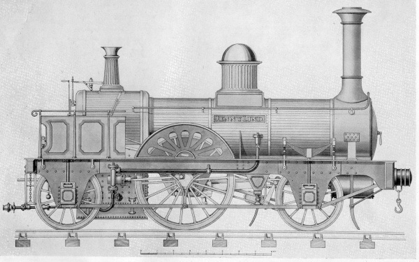
The 2-2-2 Jenny Lind
(1847), London Brighton and South Coast Railway. |
|
11. |
About 5½ tones ― a ton more than the entire weight of
the Rocket. |
|
12. |
The London and Birmingham was not the only railway
company to adopt a small engine policy and the multiple
heading of heavy trains. More famous (or infamous) was the small engine
policy adopted by the Midland Railway, which continued
following its merger with the LNWR until the appointment,
in 1932, of William Stanier as Chief Mechanical Engineer,
after which the policy was abandoned and a range of
large locomotives constructed. |
|
13. |
This
technique continued to be adopted on some long wheelbase
locomotives, notable examples in the U.K. being the
wartime Austerity and the British Railways 9F
2-10-0 heavy freight designs by R. A. Riddles. |
|
14. |
Page 135,
Robert Stephenson ― the Eminent Engineer, edited
Michael R. Bailey, pub. Ashgate, November 2003. |
|
15. |
A
Century of Locomotive Building by Robert Stephenson &
Co., 1823-1923 by James G. H. Warren (1923). |
|
16. |
EDWARD BURY F.R.S.,
M.I.C.E. was born at Salford near
Manchester on 22nd October 1794. From an early age he
was interested in machinery and showed ingenuity in
constructing models. After school he served an
engineering apprenticeship and eventually established
himself at Liverpool as a manufacturer of engines. His
firm ―
Bury, Curtis, and Kennedy ― also developed
interests in marine engines and general engineering. In
1836, Bury won a contract to provide locomotive power to
the London and Birmingham Railway. However, in 1838 the
contract was annulled and he was appointed Locomotive
Superintendent, a position in which he continued until
shortly after the merger that formed the London and North-Western Railway. In 1848 Bury was appointed Chief
Mechanical Engineer to the Great Northern Railway and
then, in 1849, General Manager, a post from which he
retired in 1850 to return to business. He died at
Scarborough on 25th November 1858, being survived by his
wife, Priscilla.
The only other designers of railway locomotives to
become Fellows of the Royal Society (that spring to
mind) were Robert Stephenson and Sir William Stanier.
Bury’s grand nephew,
Oliver Bury (1861-1946), also
served as General Manager of the Great Northern Railway,
and was a director of the London and North Eastern
Railway until shortly before his death. |
|
17. |
JAMES KENNEDY (1797-1886) was a Scottish millwright,
marine and locomotive engineer. His first connection
with the railway industry was in 1824 while in Liverpool
to supervise the installation of a marine engine, when
he met George Stephenson. This led to Kennedy’s
appointment as works manager for Robert Stephenson &
Co. In the following year he returned to Liverpool
where he eventually became foreman of the Clarence
Foundry. In 1842, Kennedy became a partner in the firm,
which was then renamed Bury, Curtis and Kennedy. He was
a founder member of the Institute of Mechanical
Engineers in 1847, and its President in 1860. |
|
18. |
Another
account of the fate of the Dreadnought/Liverpool
is given by an American author:
“Another difficulty is that
several locomotive makers each built ‘trial engines’
upon their own system or patent, and obtained the
permission of certain companies to try them on their
lines; in some cases the railway companies afterwards
purchased the engines, in others they did not. As an
instance, Mr. Bury, in 1830, built an engine named
‘Dreadnought;’ it was, by permission, tried on no less
than five lines, and then taken back to the works and
broken up, but in 1831 most of the parts were used in a
new engine named ‘Liverpool’ which by permission of the
Liverpool and Manchester Railway Company ran a trip on
that line, and was at once purchased for the Petersburg
Railroad of America, where soon after its arrival in
May, 1831, it became known as the ‘Spitfire.‘ The Author
happens to have the maker’s private number, marked upon
the drawings, corresponding with that stamped upon parts
of the engine itself, or it would have been impossible
to trace its history.”
The Locomotive
Engine and its Development,
Clement E. Stretton (1903).
The author‘s assertion appears to be borne out by the US
Treasury return of 1838 below: |
|
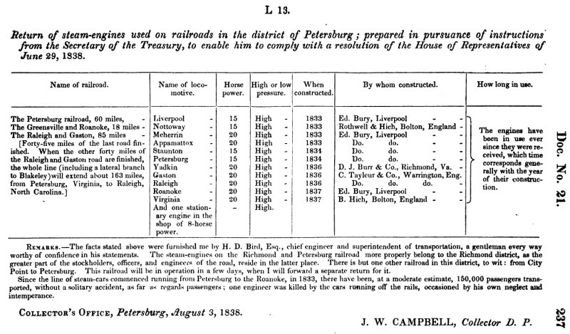 |
|
19. |
A History of Railway Locomotives Until 1831,
Chapman Frederick Marshall, Oxford University Press
1953. |
|
20. |
Professional spats are rather beyond the scope of this
paper; nevertheless, the conflicting views of James
Kennedy (Bury’s former works foreman and business
partner) and of Robert Stephenson (then President of the
Institution of Civil Engineers) concerning the
Planet’s pedigree are interesting.
The following extracts are from an exchange
that took place at a meeting of the Institution of Civil
Engineers held on 11th November, 1856, Robert Stephenson
in the Chair. In
replying to a paper ― “On the Improvement of Railway
Locomotive Stock and the Reduction of the Working
Expenses” ― presented to the meeting by DANIEL
KINNEAR CLARK,
Assoc. Inst. C.E.:
Mr. JAMES KENNEDY,
(Liverpool) through the SECRETARY,
said . . . .
“The plan of constructing locomotives with cranked axles
and horizontal cylinders, was contrived and introduced
by Mr. Kennedy, and was first applied in the locomotive
‘Liverpool,’ which was started on the 22nd of July,
1830, by Mr. Edward Bury, then of Liverpool, and was
employed in aiding in the construction of the Liverpool
and Manchester Railway. The ‘Planet,’ the first engine
constructed by Messrs. Stephenson on this plan, was not
started until four and a half months afterwards; and a
little later Mr. Hackworth set the ‘Globe’ engine to
work on the Stockton and Darlington line. The late Mr.
George Stephenson had told both Mr. Bury and Mr. Kennedy
after having seen the ‘Liverpool’ engine on the
Liverpool and Manchester Railway, that his son, the
present Mr. Robert Stephenson, had taken a fancy to the
plan of the ‘Liverpool’ engine, and intended to make,
immediately, a small engine on the same principle.
Further, the late Mr. Robert Stephenson, brother to the
late Mr. George Stephenson, had, as soon as he saw the
‘Liverpool,’ declared it was the best type for
locomotives, and that all would have to come to it
by-and-by. In fact, in the engineering world, the
‘Liverpool’ was considered a great stride in the right
direction. That engine was as efficient a machine as had
ever been made of that weight.”
Robert Stephenson had this to say in
response:
“Mr. R. STEPHENSON, M.P., ―
President, ― remarked, that the working drawings of the
‘Planet,’ which was admitted to have been the type of
the engines employed on the Liverpool and Manchester
line, had been made, and the engine constructed under
his direction, without any reference to or knowledge of
the ‘Liverpool.’ These facts could be fully confirmed by
those who were confidentially employed upon the engine
at the time. Neither was there any analogy between the
two machines, for the ‘Planet’ had a multitubular
boiler, the fire being urged by a blast-pipe, and the
cylinders, which were as nearly horizontal as their
position would permit, were fixed inside, or between the
frames, because it was only by such an arrangement that
they could be placed within the smoke-box, where it was
considered desirable to fix them, in order to prevent
the condensation of the steam in the cylinders, and the
consequent loss of power. This had been resolved upon
from information given to Mr. R. Stephenson by the late
Mr. Trevithick, who in the course of some experiments,
had built a brick flue round the cylinder, and had
applied the heat of a fire directly to the metal, with
very beneficial results as regarded the economical use
of steam. With the cylinders in the smoke-box, a cranked
axle was indispensable, and there was not anything new
in its use in locomotives, for the ‘Novelty’ by
Braithwaite and Ericsson, had one in 1829. Horizontal
cylinders and cranked axles had also been commonly
employed long previously, in Trevithick’s, Gurney’s, and
almost all the other locomotives for tumpike roads. The
statements alleged to have been made by the late Mr.
George Stephenson, as to the priority of the peculiar
arrangement of the ‘Liverpool,’ in this respect, or
those asserted to have proceeded from the late Mr.
Robert Stephenson, as to its being the best type for
locomotives, could not therefore be admitted to be
correct.”
Minutes of Proceedings
of the Institution of Civil Engineers, Volume 16, 1857.
It is interesting to note that Stephenson
fails to mention Hackworth’s Globe ― also a
crank-axle, inside, double horizontal cylindered
locomotive ― which was building in his Company’s
Newcastle workshops while the Planet was also
under construction. |
|
21. |
From 1830 to 1833 (incl.), Robert Stephenson & Co.
supplied 25 locomotives, Edward Bury 1 (the Liver)
and 5 were supplied by other firms. |
|
22. |
Later to attract considerable fame in the railway
industry as the Vulcan Foundry. |
|
23. |
. . . . some of which was acrimonious and public. The following extract is from “Inland
Transport”, an article published in October
1832 in the influential periodical, The Edinburgh
Review. The credibility of its author, Dr. Dionysius
Lardner, is often called into question (and sometimes
held up to ridicule) on railway matters. While monopoly
and cartel present commercial dangers of which some, at
least, of the Railway’s directors were keenly aware, in
his article Lardner overlooked the benefits to be had
from standardizing on a proven product at a time when
there was great diversity extending to freakishness
in the design of railway locomotives, as the Rainhill
Trials demonstrated:
“There can be no doubt that this method of exciting
competition
[the Rainhill Trials]
produced a favourable effect at the time; and most
probably the enterprise would not have commenced with
the same degree of success without some such expedient. Nevertheless, it has had also some injurious
consequences. It will be easily understood, that an
engine may possess great capability of improvement, and
yet fail upon a single trial; or it may fail even from
accidental causes, unconnected with any defect either in
its principle or in its details. The complete success of the engine furnished by Mr.
Stephenson appears at once to have fascinated the
Directors; and whether intentionally or not, the fact is
indisputable, that the monopoly of engines has ever
since been secured to the manufacturer of this
particular form of machine
[Robert Stephenson & Co.]. Even when Mr. Stephenson was
unable himself to supply engines as fast as the Company
required them, and other engine-makers were employed, it
was under the most rigorous conditions, to construct the
engines upon the same principle and in the same form, or
nearly so, as that which Mr. Stephenson had adopted.
Experience, the great parent of all invention and
improvement, so far as the railroad afforded it, has
thus been exclusively confined to one particular form of
engine. Under the influence of this, a succession of
improvements, as might have been expected, have been
made by the ingenious inventors of the engine above
described. These improvements consist partly in the
relative proportion and strength of the parts, and
partly in the arrangement of the cylinders and their
action upon the wheels; but all have been suggested by
the results of experiments, upon such a scale as was
altogether unattainable by any part of the vast stock of
national talent excluded from the road by those measures
of the Directors, which limited the engines employed to
a single form. The whole enterprise of the country was
therefore paralysed, in as far as the powers of this
road were concerned; with the exception of one
individual, who was fortunate enough to obtain a field
of exertion, which it must be admitted he did not fail
adequately to improve. ” |
|
24. |
‘d’ was the
symbol used to denote an old penny. |
|
.htm_cmp_poetic110_bnr.gif)