|
NOTES AND
EXTRACTS
ON THE HISTORY OF THE
LONDON & BIRMINGHAM RAILWAY
CHAPTER 9
CONSTRUCTION ―
THE EUSTON EXTENSION
THE SECOND ACT (1835)
While the design and legal work necessary to
build the Railway along the route authorised in the 1833 Act was in
progress, the Board had second thoughts about the location of their
London terminus. Following some debate (initiated by Stephenson)
it was decided to change the location of the
London terminus from Camden Town (the site authorised in the 1833 Act)
to Euston Grove, about a mile to the south-east. This
change
required the authority of a further Act of Parliament, a considerable investment in
land, and extensive civil engineering work necessary to cut through a
built-up area.
It is to the benefit of
today’s travellers that those
long forgotten Board members considered the outlay worthwhile.
On the 3rd July 1835, there passed into law . . . .
“An Act to enable the London and Birmingham
Railway Company to extend and alter the Line of such Railway and for
other Purposes relating thereto . . . .
. . . . II. And be it further enacted, That
it shall be lawful for the said Company and they are hereby
empowered to make an Extension of the said Railway . . . .
commencing in a Field on the West Side of the High Road leading from
London to Hampstead, being the Site of the Depot or Station intended
to be made for the Use of the said Railway, in the Parish of Saint
Pancras in the County of Middlesex, and thence passing across the
Regent’s Canal between the First and Second Bridges Westward of the
Lock at Camden Town into and through the said Parish of Saint
Pancras, and terminating in a vacant Piece of Ground in a Place
called Euston Grove, on the North Side of Drummond Street near
Euston Square in the same Parish, and which said Extension of
Railway will pass through or into the Parish of Saint Pancras in the
said County of Middlesex.”
5 & 6 Gulielmi IV. Cap. lvi., RA 3rd
July 1835.
Section III. of the Act also authorised alterations to the route at
Wolverton, Weedon and Brockhall, by which two tunnels and a bad
curve were avoided.
The new station faced the Euston Road, [1] which became, de facto, the barrier for railway
termini approaching London from the north and west; King’s
Cross, Saint Pancras, Marylebone and Paddington stations are sited
along the Euston Road and its extensions.
――――♦――――
THE CAMDEN INCLINE
With an average gradient of 1:85, the ‘Euston
Extension’ ― also known as the ‘Grand Excavation’, but now generally
referred to as the ‘Camden Incline’ ― was to become the one section on the
Railway where the ruling gradient of 1:330 could not be
maintained. As built, the gradients along the sections of the
Extension were:
|
Gradient, Euston to Camden.
There are 80 chains to a statute mile [2] |
|
Chains |
|
Gradient |
|
Section |
|
12 |
………… |
Fall 1 in 156 |
|
Euston to Hampstead Road |
|
13½ |
………… |
Level |
………… |
ditto |
|
16½ |
………… |
Rise 1 in 66 |
………… |
Hampstead Road to Crescent Place |
|
17 |
………… |
Rise 1 in 110 |
………… |
Crescent Place to Park Street |
|
9 |
………… |
Rise 1 in 132 |
………… |
Park Street Bridge |
|
16 |
………… |
Rise 1 in 75 |
………… |
Park Street to Regent's Canal |
 |
|
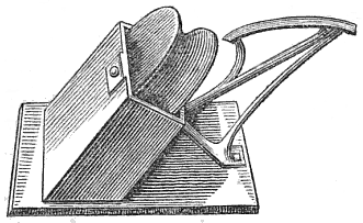
An artist’s impression of a
roller from the Camden Incline. |
|
LONDON AND
BIRMINGHAM RAILWAY
. . . . The stationary engine at Camden-town requiring
some trifling repair, the morning train on Saturday last
was worked up the incline by locomotive engines, which
were to take the trains on from the station last
mentioned when more than one engine is required. In the
present case it was expected that one would have
sufficed, and one accordingly was attached in front of
the train (the eleven o’clock), but a drizzling rain
falling, the power, shortly after the train started, was
found inadequate, and a second engine was despatched to
its assistance. When it reached the tail of the train,
the wheels of the engine in front unfortunately slipped,
and a partial collision occurred. It was, however,
sufficient to occasions a severe contusion on the head
of Hallam, one of the passengers in the last carriage of
the train. |
|
The Era,
30th June 1839. |
Due to its steepness and the inconvenience of manoeuvring
locomotives in the confines of the planned passenger terminus, it
was decided to work the Euston Extension, not with locomotives, but with an endless cable system powered by
a pair of stationary steam engines. These were located at the top of the Incline
at Camden Town:
|
“This rope is ten thousand nine
hundred and fifty feet in length, seven inches in
circumference, and weighs about eleven tons twelve
hundred weight; it runs over hollowed iron sheaves,
turning on an axle in an iron frame, placed at distances
of twenty-four feet. The mode, however, in which the
engineer has enabled the engine to draw the carriages
round a curve of considerable sharpness, is at once most
ingenious and beautifully simple . . . . As the curve
becomes sharper, the above pulley is placed the more out
of the centre of the line of rails over which the
carriages are passing ― and the nearer to the convex
side of the turning, the guard being towards the concave
side of the wall; consequently, as the rope is fastened
to the centre of the carriage, it is drawn into the
centre of the line as the carriage passes each sheave,
and when this is sufficiently passed to allow the rope
to drop by its own weight, it falls upon the guard and
slides at once into the groove of the sheave.”
Freeling's
Railway Companion, from London to Birmingham,
Arthur Freeling (1838). |
In July 1836, a tender was accepted from the engineering firm of
Maudslay, Sons and Field to supply two 60 h.p. condensing
steam engines capable of drawing trains up the Incline at 20 m.p.h. These were
installed in a subterranean engine house together with their boilers and the winding gear they were to drive.
The only hint that the traveller had of this machinery was a pair of
tall chimneys,
described by Francis Wishaw as
being of “beautiful symmetry and exquisite workmanship”. |
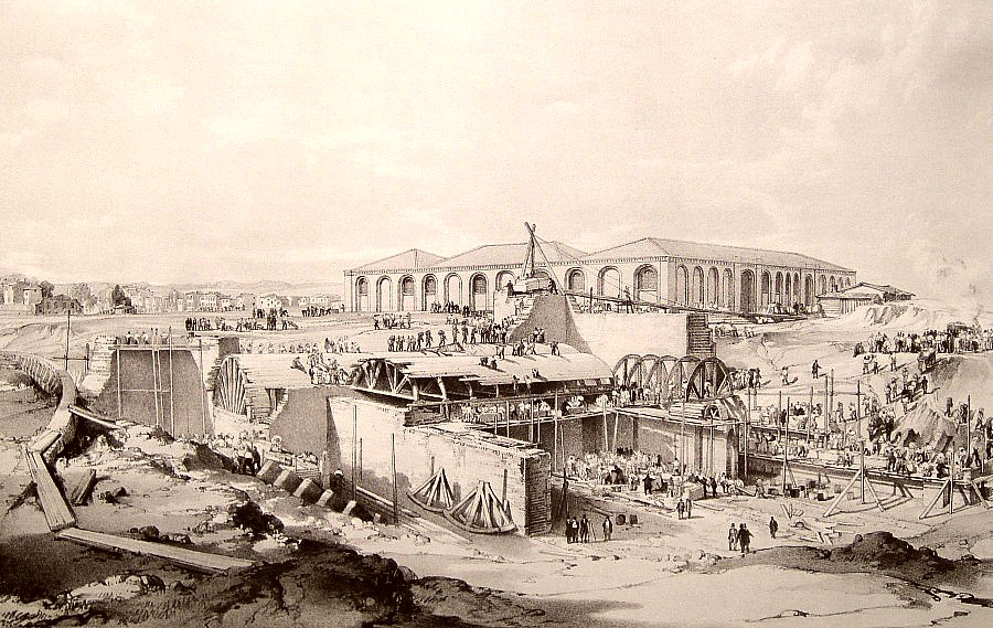
Camden Town Depot. Stationary
engine house in the course of erection,
by John Cooke Bourne, May 1837. The original engine house is shown
in the background.
|
In his history
of the line, Peter Lecount claims that locomotives were
capable of working the Extension, but were prevented from so doing
by the legislation, which aimed to prevent the nuisance caused by
their noise. Lecount appears to be referring to section 50 of the
1835 Act, which, while not referring to locomotive engines
specifically, can be read to impose the restriction to which he
refers:
“L. And be it further enacted, That the
said Company shall not fix, erect, or build, or otherwise work or
use, or permit or suffer any other Person or Persons to fix, erect,
or build or otherwise suffer to be worked or used, any Steam or
other Engine, Forge or Manufactory, on any Part of the Land or
Ground purchased of and conveyed to them by the said Charles Lord
Southampton by the Deed Poll dated the Third Day of January One
thousand eight hundred and thirty five, which may be or cause any
Nuisance, Annoyance, Damage, or Disturbance to the said Charles Lord
Southampton, his Heirs or Assigns, or any of his or their Lessees or
Tenants in the said Parish of Saint Pancras, without first obtaining
the Consent in Writing of the said Charles Lord Southampton, his
Heirs or Assigns.”
5 & 6 Gulielmi IV. Cap. lvi.,
R.A. 3rd July 1835.
That said, locomotives were used to work the Incline when
operation of the winding engines was suspended for repair or
maintenance. In all likelihood the noise of the
heavy endless cable being dragged over a long succession of squealing
rollers was probably comparable in nuisance to that of a steam
locomotive under load. |
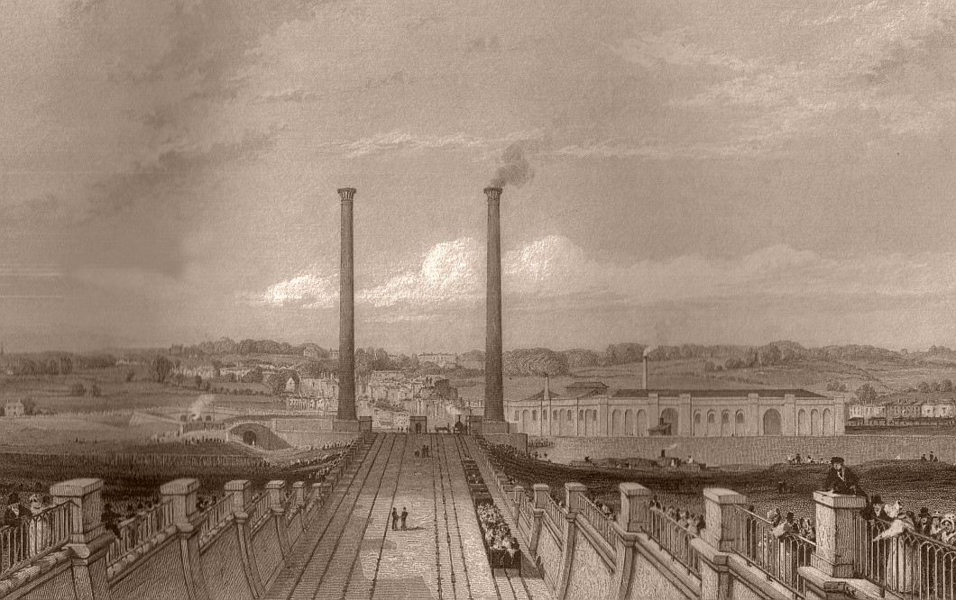
The stationary steam engine chimneys and the
locomotive workshops (right background), looking towards Camden. By E. Duncan, 1838.
Barges on the Regent’s Canal are just visible below the
workshops ― the canal bridge marked the summit of the incline.
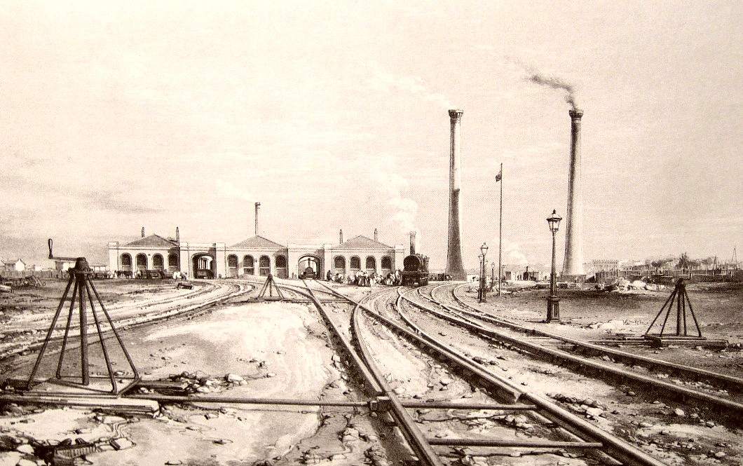
Camden Town Depot. Locomotive Engine
House, Chimneys of Stationary Engine, with rails, eccentrics, &c. ― looking
towards London.
By John
Cooke Bourne, 1838.
|
“The land being on a considerable rise
outwards from London is worked, as before named, by endless ropes
passing over pulleys in the middle of the tracks, which ropes are
set in motion by the stationary steam engines at Camden Town. Great
precaution is required in attaching the carriages to the rope; and
this is generally done by one man, who is trained for that purpose. The way in which he effects the fastening is by means of a small
rope, called a ‘messenger’, having a slip knot at one end, which he
passes over the rope, and holds the other in his hand as he stands
on the foremost carriage in order to release the train when it
reaches Camden Town, or in case of accident. By a signal given to
the engineer, the engines are stopped in an instant. The train is
generally drawn up this length of railway in three or four minutes,
during which time the passenger passes under several very handsome
stone and iron bridges and galleries; the most extensive are those
under the Hampstead-road and Park-street . . . . When the train
arrives at the Iron Bridge which carries the line over the Regent’s
Canal, the carriages are detached from the rope, and allowed to run
along the line till they meet the locomotive engine by which it is
afterwards propelled.”
The London and Birmingham Railway,
Thomas Roscoe and Peter Lecount (1839).
It was during this period that the need for a signalling system
between Euston Station and the Camden stationary engine house led (on the 25th July 1837) to a trial of Cooke and Wheatstone’s electric telegraph, of
which more in the next chapter. However, on grounds of cost and
reliability the Directors opted for a pneumatic signalling system,
which, at Euston, was used to force air along a tube to sound an organ pipe
in the Camden stationary engine house. An identical system
operated in the opposite direction, alerting those at Euston of the impending arrival of an up-train:
“As soon as the reeking engine-funnel of an
up-train is seen darting out of the tunnel at Primrose-Hill, one of
the Company’s servants stationed there, who deals solely in
compressed air ― or rather who has an hydraulic machine for
condensing it ― allows a portion to rush through an inch iron pipe;
and he thus instantaneously produces in the little signal-office on
the up platform of Euston Station, where there is always a signal
man watching by night as well as by day, that loud melancholy whine
which has just arrested our attention, and which will continue to
moan uninterruptedly for five minutes. The moment this doleful
intimation arrives, the signal-man, emerging from his little office,
touches the trigger of a bell outside his door, which immediately in
two loud hurried notes announces to all whom it may concern the
arrival at Camden Station of the expected up-train; and at this
moment it is interesting to watch the poor cab-horses, who, by
various small muscular movements, which any one acquainted with
horses can readily interpret, clearly indicate that they are
perfectly sensible of what has just occurred and quite as clearly
foresee what will very shortly happen to them.”
The London Quarterly Review,
Volume LXXXIV (1848).
The cable system remained in use until 1844, when
it was replaced with locomotive haulage:
“Upon trial it was found, that the
locomotive engines could surmount the inclined plane between Euston
and Camden Stations with the ordinary trains, and that with the
assistance of a second engine, the heavy trains could also be passed
to Camden Station. A saving of ten minutes in time was the result,
as well as economy in the cost of working the stationary engines and
inclined-plane rope. After numerous successful trials, the engines
and rope were, in April, 1844, abandoned, and in course of time the
stationary engines were sold, and they are now doing duty in a flax
mill in Russia.
The saving in time thus effected was of little, or no value; and
attention being directed to the locomotive stock, it was found, that
even with two engines, the required speed could not be attained with
the heavy trains. A number of locomotive engines of large dimensions
were ordered, and by degrees the stock has been brought to consist
almost entirely of this class.”
Paper by R. B. Dockray published in
the
Proceedings of the Institution of Civil Engineers, Volume 8
(1849). |
――――♦――――
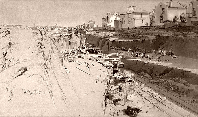
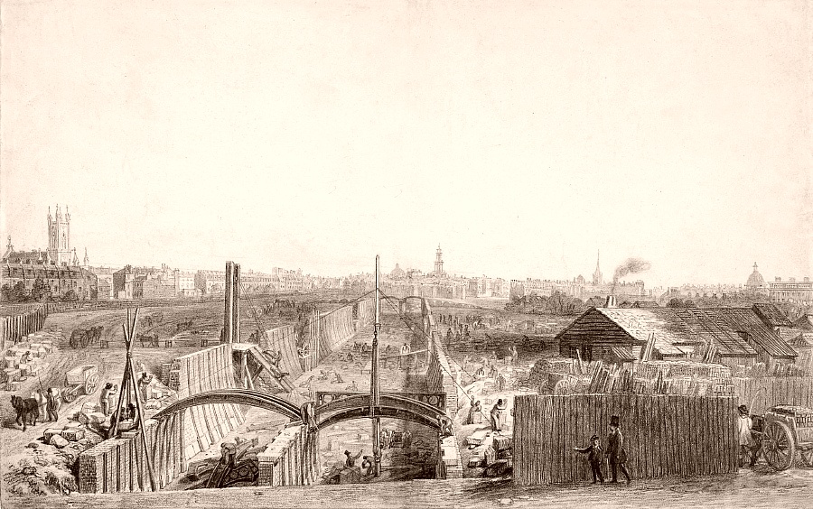
BUILDING THE EXTENSION
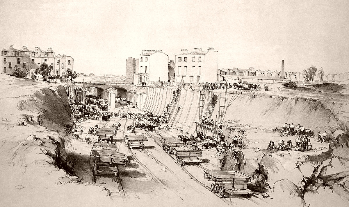
Excavation at Park Village, showing the work
in progress.
John Cooke Bourne, September 1836.
|
“The first shock of a great earthquake had,
just at that period, rent the whole neighbourhood to its centre. Traces of its course were visible on every side. Houses were knocked
down; streets broken through and stopped; deep pits and trenches dug
in the ground; enormous heaps of earth and clay thrown up; buildings
that were undermined and shaking, propped by great beams of wood. Here, a chaos of carts, overthrown and jumbled together, lay topsy
turvy at the bottom of a steep unnatural hill; there confused
treasures of iron soaked and rusted in something that had actually
become a pond. Everywhere were bridges that led nowhere;
thoroughfares that were wholly impassable; Babel towers of chimneys,
wanting half their height; temporary wooden houses and enclosures,
in the most unlikely situations; carcases of ragged tenements, and
fragments of unfinished walls and arches, and piles of scaffolding,
and wildernesses of bricks, and giant forms of cranes, and tripods
straddling above nothing. There were a hundred thousand shapes and
substances of incompleteness, wildly mingled out of their places,
upside down, burrowing in the earth, aspiring in the air, mouldering
in the water, and unintelligible as any dream. Hot springs and fiery
eruptions, the usual attendants upon earthquakes, lent their
contributions of confusion to the scene. Boiling water hissed and
heaved within dilapidated walls; whence, also, the glare and roar of
flames came issuing forth: and mounds of ashes blocked up rights of
way, and wholly changed the law and custom of the neighbourhood. In
short, the yet unfinished and unopened Railroad was in progress . .
. . ”
Dombey and Son, Charles
Dickens (1846-8).
On the 9th December 1835,
William and Lewis Cubitt were awarded the contract to build the Euston
Extension [3] for the sum of £76,860, [4]
the contract including a penalty to be invoked should the work not
be complete by the 1st January 1837. Stephenson appointed Charles Fox Resident Engineer
although he, himself, maintained a close interest in the progress of
the work. |
|
 |
|
Above: Park Street, Camden Town, 18th September 1836.
Below: Park Village, 26th August 1836.
|
|
 |
|
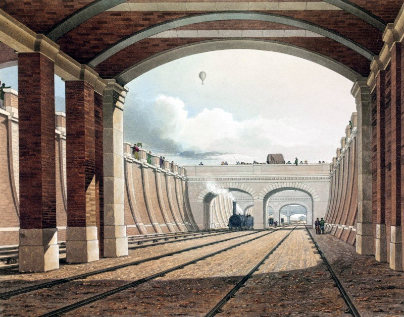
Park Street Bridge.
Note the endless cable in
the centre of the track and the railway ‘policemen’, forerunners of
today’s signalmen. |
|
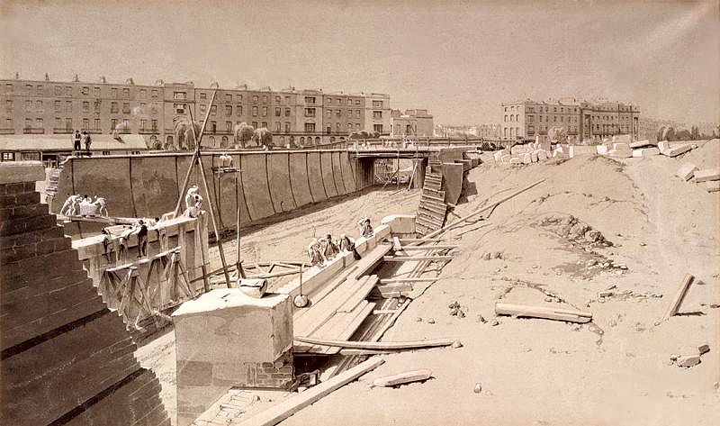
Partly to economise on land purchase and bridge construction
(along its short length, the line originally passed under seven bridges) most of the Extension lies in a walled cutting, the walls
being of stronger than usual construction throughout. The
thickness of the walling can be seen in Cooke Bourne’s drawing below.
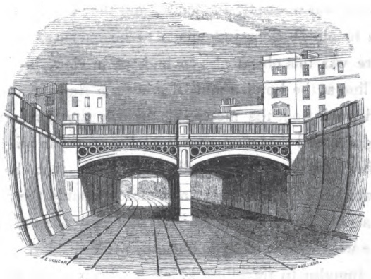
Hampstead Road Bridge from the
Camden side.
John Cooke Bourne, 11th August
1836.
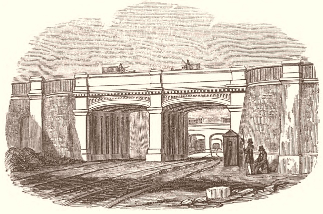
LONDON FIXED ENGINE
PLANES. ― From the Euston station to
the Camden depot there are four lines of way, which are carried as
far as Park Street between retaining walls: the clear width occupied
here is about 56 feet; the walls are about 19 feet in height, and
are built to a curved batter, with a radius of about 60 feet, the
versed sine being about 4 feet 10 inches; lowest part of the
foundation is 7 feet from the level of the rails; the thickness of
brickwork decreases from the footings upwards, being at the bottom 3
feet 11½ inches, and at the top 2 feet 7½ inches. The whole length
of these extends to upwards of 2,200 yards.
In this length there are seven bridges and archways over the
railway, each of which is in two spans. Some of these bridges are
built of brick and faced with stone; and others have iron ribs
resting on brick piers.
From Park Street to the Regent’s Canal bridge at Camden Town the are
near the general surface of the ground; and the railway is enclosed
on either side with neat iron railing and pedestals of brick resting
on dwarf walls.
As these planes are considerably curved in some portions, both
vertical sloping sheaves are used for the rope; they are fixed in
cast iron cases embedded in the ballasting.
The Railways of Great Britain and
Ireland, Francis Wishaw (1842).
Due to the section
between Park Street and the Hampstead Road being driven through
London clay, Stephenson’s specification laid down exactly how the
excavation was to proceed ― on no account was the its face to be carried on more than 40 feet in advance of the
completed retaining wall without the Engineer’s written permission. This
stipulation took into account the characteristic of London clay to
stand for a short time after being cut, but then to bulge outwards with
force as it
absorbed moisture:
“One of those extraordinary difficulties to
which cuttings through the London clay must ever be liable, occurred
in this excavation. To facilitate the removal of the material, a
gullet had been
formed and a temporary railway laid down, when a season of excessive
wetness set in; the works however proceeded with that perseverance
which characterises the resident engineer Mr. Fox ― when one morning
the treacherous material gave way, the gullet was filled up, and the
labour of weeks (estimated at a cost of about £800) was destroyed in
a night, by an accident which could not have been anticipated, as no
previous experience had enabled engineers or directors to provide a
preventative, or to expect such a result . . . . One hundred and
eighty thousand cubic yards of clay were removed from this cutting.
During the progress of this portion of the line, the Company had no
less than 1,000 men employed upon this mile and a quarter of ground.”
The Railway Companion, from London
to Birmingham, Arthur Freeling (1838).
The plans and specifications for the Extension illustrate the
substantial construction of its retaining walls:
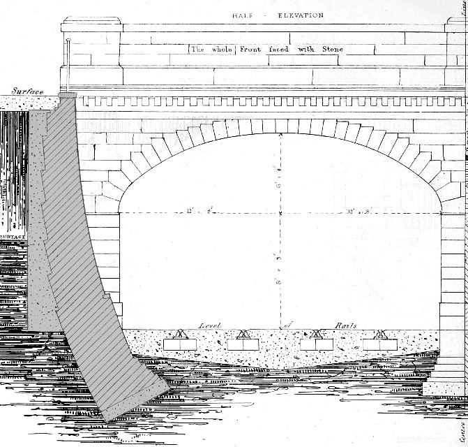
Bridge for intended street on the
Duke of Bedford’s estate upon the Exn. L & B Railway.
The retaining wall, shaded grey, is typical of those built along the
Extension.
“Sections
and Elevations of the Retaining Walls are shewn on the various
drawings.
The faces of these walls will be a Curved
Batter; [5]
the radius of this batter will be 50 feet, giving an average batter
of 2 inches per foot on 20 feet in every case, excepting in the
walls from Crescent Place to Park Street, which have a radius of 61
feet 8 inches, being an average batter of 2 inches to a foot on 20
feet. The whole of the brickwork of the walls will be laid in
courses radiating from the supposed centre of the curve of the
batter. The walls will increase in thickness the nearer they are to
the foundations, by half brick offsets, and the footings will
consist of steppings of two courses of brick, projecting one quarter
of a brick.
One foot thickness of Concrete will be placed under the footings of
the walls, it will project 6 inches from the footings in the front,
and be flush with the neat work behind.
The space at the back of the walls shall be well Punned [6]
in with clay. The faces of the walls will be broken at intervals of
16 feet, or thereabouts, as near thereto as consistent with dividing
a given length of wall into an equal number of parts, by Pilasters 4
feet by 4 inches wide, projecting half brick, built and bonded with
the rest of the wall. Counterforts [7]
will be built at the back of the wall, equidistant between the
pilasters and bonded into the wall. A stone plinth 6 inches thick
must be built in at the required height, and the wall above it will
recede ¼ of a brick from the face of the plinth.”
An extract from Stephenson’s work
specification, published in Railway Practice, S. C. Brees
(1838).
In addition to the work involved in excavating and walling the
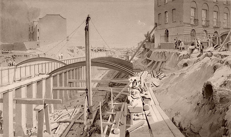
Extension, the line passed under seven road
bridges and crossed the Regent’s Canal on an iron bowstring bridge,
probably designed by Charles Fox . . . .
The Regent’s Canal Bridge.
“The earliest railway bridge on the
bowstring principle is that over the Regent’s Canal, near Chalk
Farm, on the London and Birmingham Railway.
It is composed of three main ribs of cast-iron open panel work,
whose outline is parallel, but which includes an arc extending to
its extremities of length and depth, and intersecting the vertical
bars which form the panels. The span is 50 feet and the height of
the ribs 10 feet. The section of each rib is in the form of a hollow
rectangle 2 feet 11 inches wide, and the space between its sides is
filled with diagonal bracing-frames 5 feet 10 inches apart. The
railway is carried by cast iron girders of the fish-bellied shape,
28 feet between bearings and 1 foot 10 inches deep in the middle;
they are suspended from the bracing-frames in the main ribs by
wrought-iron suspension rods 2¼ inches diameter; there being sockets
in the bracing-frames to receive their upper ends, and in the ends
of the cross-girders to receive their lower ends.
The centre main rib performs double duty; and its bracing-frames
have double sockets, and carry two suspension rods. In addition to
the ribs themselves in resisting the strain of the load there are
longitudinal tie-bars under each rib, there being four under each
outside rib in a horizontal row, and eight under the centre rib in
two horizontal rows. These tie-rods are secured to the bearing ends
of the main ribs, and are in three lengths, each united by sockets, gibs, and keys. Upon the cross-girders are oak sleepers for the
rails; and the entire space between the rails is filled in with
cast-iron plates perforated in the form of trellis-work. The
outsides of the outer ribs are ornamented with cast-iron mouldings
and fret-work. This bridge is of very bold design and certainly a
novelty as regards construction.”
The Encyclopaedia Britannica,
Vol. 12 (1856).
Alas, this fine bridge is long gone:
“The works associated with the original
station included bridges to carry various existing roadways over the
line and to carry the line over the Regent’s Canal. Of these
bridges, three are illustrated and described by Simms. [8]
They are the Stanhope Place Bridge, the Park Street Bridge, and the
bridge over the Regent’s Canal. The Stanhope Place Bridge,
consisting of two segmental masonry arches, was removed when
Stanhope Place was diverted into Mornington Terrace in the
’nineties. The Canal bridge has also been destroyed, but that over
Park Street still exists, as does that carrying Granby Terrace. The
two-arched Ampthill Square road bridge was taken down in 1898 and
replaced by girders. The bridge over Wriothesley Street, the first
to be built, had been demolished as early as about 1846-47, when
Wriothesley Street was closed. The cutting running south for a short
way from Park Street and spanned by segmental cast-iron struts, is
the original structure of 1836-37.”
Survey of London: volume 21: The
parish of St Pancras part 3 (1949). |

Above: the iron bridge over the Hampstead
Road.
Below: the same bridge under construction.
George Scharf, May
1836.
View taken from under the
Hampstead Road Bridge,
Looking towards the station at Euston Square, 18th September,
1837.
|
|
 |
|
The Hampstead Road
Bridge. |
“From Euston Square to Camden Town the
Railway is formed by a wide cutting or trench, about eighteen or
twenty feet deep, the sides of which are composed of beautifully
executed brick work, having an iron balustrade at top, which when
the trees and shrubs of the adjoining gardens have sprung up, will
form a pleasing object . . . . The whole of this length is
excavated from the London clay; and the walls which form the sides
are curved, in order to resist the inward pressure; they are as much
as three bricks thick at the top and seven at the bottom; the number
of bricks used in forming these gigantic walls was about sixteen
millions.”
The London and Birmingham Railway, Roscoe and Lecount (1839).
By July 1837, the Euston Extension was complete and the first experimental passenger
journey to be made on the London and
Birmingham Railway took place. It was not without incident ― from the casual
manner in which derailments are referred to, it seems that they, at
least, were not
uncommon:
LONDON AND BIRMINGHAM RAILWAY.
“Thursday week the directors gave an excursion to a select
party of their friends by way of experiment preparatory to the
public opening of the railway from the station at Euston grove to
Box-moor and back.
At one o’clock (the hour appointed for starting)
a train, consisting of eleven carriages, left the station, gliding,
by its gravity, down a gently inclined plane for 200 or 300 yards,
when the engine was immediately attached, amidst the loud and hearty
cheers of a great number of spectators outside the line. The
distance (25 miles) was performed in an hour and eight minutes. At
Box-moor an elegant lunch was provided for the company in an marquee
pitched on a neighbouring rising ground. The weather was fine, and
every one seemed delighted with the scene. A second train of twelve
carriages left town at two o’clock, and reached Box-moor at few
minutes after three.
The train which started at one left for town at
four; but in consequence of some mismanagement as to the supply, we
believe, of water to the boiler, and the wheels of the engine
getting off the rail, sundry stoppages occurred by the way, which
protracted its arrival till ten minutes to six. Just as this
train had reached the terminus at the back of Euston square, the
engine having been disengaged, but the impetus still continuing at a
considerable velocity, the men whose duty it was to check the motion
by working what are technically called the ‘breaks,’ not being
sufficiently expert, or miscalculating their power, the carriages
came with frightful force against the barrier wall at the extremity
of the line, dashing it to atoms, and causing a rebound which
frightened all and damaged not a few. The concussion was so
great that those sitting opposite in the different carriages being
thrown against each other with great violence, we are sorry to say
some instances of serious injury occurred. Among others Lord
Hatherton received a severe bruise on the cheek; Mr. N. Calvert,
formerly M.P. for Hertfordshire, violent contusions on the face; two
gentlemen and a lady had their noses broken; others lost their front
teeth, and several sprained their wrists and arms.”
The Bucks Herald, 22nd July 1837.
Other than giving a couple of clues, the article’s author fails to
mention travelling over the Camden Incline. After the
stationary engine had hauled the train up the Incline from Euston,
the writer’s reference to “gliding
by gravity, down a gentle incline plane” refers to the final
section beyond the Regent’s Canal bridge, down which the
carriages descended under gravity to Camden Depot where a locomotive
was attached. On the homeward
journey the locomotive was detached near the top of the Incline.
The coaches were then pushed to its summit, from where they descended
to Euston under gravity, the descent being controlled by the
carriage brakes ― or in this particular case, by collision with the barrier wall.
――――♦――――
FURTHER PROBLEMS WITH LONDON CLAY
In Railway Practice, Dempsey drew on
examples to provide sound advice on the dangers of earth swelling
when saturated, even when retained by substantial brickwork:
“Many
instances are recorded of the failure of these structures, which has
commonly resulted from the saturation and consequent swelling of the
earth behind them; and these effects have occurred frequently,
despite the most judiciously-selected forms and materials, and the
best attainable system of back drainage. Indeed, unless the material
be adapted to stand by itself, be thoroughly impervious to water, or
so completely drained that very little reaches the back of the wall,
it is certain that this uncontrollable agent will make its way
through the work, and produce sooner or later the disastrous
consequences which have already marred the designs of railway
engineers.”
The Practical Railway Engineer,
George Drysdale Dempsey (1855).
The Primrose Hill Tunnel was not to be
Stephenson’s only run-in with London clay. By 1843 (six years
after the Extension had opened), the clay to the rear of the Extension’s western wall
had become
saturated through inadequate drainage. Such was the force it
then exerted, and despite great care having been taken in the wall’s design,
sections of it were thrust forward. The remedy that Stephenson
applied was improved drainage, to which he added reinforcing struts between the facing
walls at top and bottom, and vaults behind the upper
sections of the western wall:
“This
excavation intersects the London clay, the dip of which at that part
inclines downwards towards the east. The consequence is, that the
wall on the west side is required to sustain constantly an enormous
thrust, which is, of course, much increased when the clay becomes
swollen by absorbing water from the western environs lying towards
Primrose Hill, which are above the level of the top of the cutting.
This wall of the excavation, although built of great thickness, with
a curvilinear batter, substantial footings, and bedded and backed in
good concrete, and withal, carefully built, showed early symptoms of
its inability to withstand the pressure acting behind it; and the
upper part of the wall, the weakest, becoming displaced to a
considerable extent (in some instances more than 12 inches), it was
deemed necessary to adopt the ready means of a temporary support
offered by timber shoring.
Meantime, holes of 6 or 8 feet in length, and 3 inches in diameter,
were bored through the wall and the backing, and inclining upwards
by the apparatus known as ‘Watson’s Boring Machine’; and the
perforated tubes used by the inventor of that machine were then
introduced, and fixed into the wall. By this precaution much of the
water was prevented from accumulating within the clay; and in some
parts the clay appeared to be in some degree drier than it was
previously; but in other parts the frequent discharge of water
through the wall showed the activity of the mischievous agent, and
it became highly necessary to adopt so permanent method of giving
support to the failing wall, and preventing any further alteration
of its position.
Under the able direction of Robert Stephenson, Esq., the Consulting
Engineer to the Company, and R. B. Dockray, Esq., the Resident
Engineer, three measures were promptly adopted, which have been
found to answer their purpose admirably. These measures were:
First, introducing cast iron girders of a large section
between the eastern and western walls, so as to serve as abutments
for the latter against the former.
Second, embedding strong wooden horizontal foot-struts
between the footings of the two walls, so as to prevent the lower
part of the western wall from yielding forward, when the upper part
was strengthened by the cast iron girders.
Third, reducing the weight pressing against the western wall
by excavating the clay, and constructing spacious vaults with strong
walls.
Besides these arrangements, a large side drain was constructed near
the western wall, which drain received the water, by means of cross
channels formed with drain-tiles, from the clay behind the wall;
perforations in the wall being formed for that purpose.”
Discussion at the Institution of
Civil Engineers, reported in
The Practical Railway Engineer,
G. D. Dempsey (1855). |
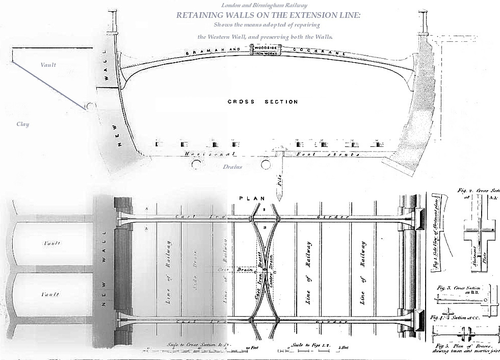
Drawing showing remedial action in
the Euston Extension following damage to the retaining walls by saturated London clay, ca. 1842-3.
The diagram shows, on the western side, the vaults; also the
cast-iron girders placed across the cutting, braced with transverse
cast-iron struts.
From Railway Practice, by J. D. Dempsey (1845).
|
The above (time ravaged) drawing illustrates the remedial action
that Dempsey describes;
note also (on the plan) the cast-iron bracing between the girders.
――――♦――――
DEVELOPMENTS AT CAMDEN DEPOT
Because the decision to extend the line from Camden Town to Euston
was taken shortly
after the 1833 Act had been obtained, Camden never developed into a
major passenger station ― it did, however, become a major depot. Other than housing the stationary steam
engines and winding gear for working the Incline, Camden fulfilled a number of other
important roles, particularly with regards to goods traffic:
“The works on the old station
were,
1st, the stationary engine-house, which
consisted of vaulting under the railway adjoining the Regent’s
Canal; the boiler-houses opening to the railway, and two very
handsome chimneys, which formed conspicuous objects in the district.
Two condensing engines of 60 H.P., built by Messrs. Maudslay and
Field, were used to draw the trains from Euston up the inclined
plane, (averaging 1 in 85) to Camden Station, whence they proceeded
on their journey by locomotive power.
2nd. A locomotive engine-house capable of
accommodating fifteen engines, together with the requisite fitting
shops and offices.
3rd. Sixteen coke ovens.
4th. Two goods sheds and stabling, together
with a small accommodation for stores, and a shop for repairs of
waggons.”
Paper by R. B. Dockray published in
the
Proceedings of the Institution of Civil Engineers, Volume 8
(1849).
Some of the Company’s offices were also located at Camden in,
it would seem, insalubrious surroundings:
“After
serving a few months in the audit office, and in the opening of the
through line to Birmingham, I was drafted from the Manager’s office
to Camden Station, in connection with the Stores and
Construction Departments. This was a change for the worse as regards
my personal comfort. The office was a rough wooden erection, with an
earthen floor, and contained, by day, myself in my great coat, the
stores of all kinds, a table, a small cabin stove, and the mice. Chalk Farm was in the country then, and I had to prepare my meals at
the small stove, and to consume them assisted by the mice, who
evidently had a great contempt for my presence. The place was always
muddy. The station had been raised from the road by the earth from
the Primrose Hill Tunnel, and this new clay produced a Slough of
Despond, which I have only seen equalled at the Royal Agricultural
Show, at Kilburn, a few years ago.”
Fifty Years on the London & North
Western railway, David Stevenson (1891). |
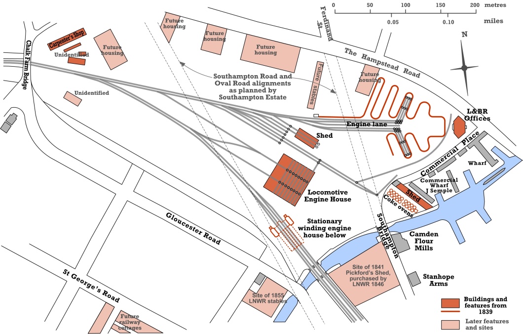
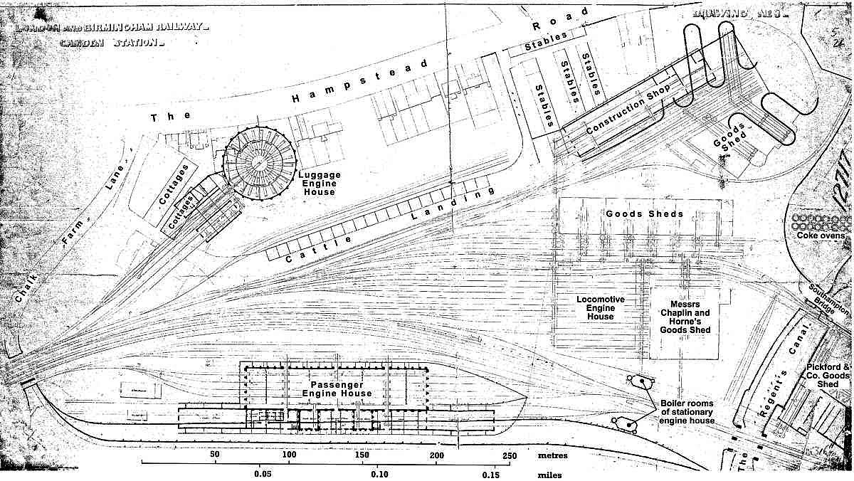
Camden Depot in 1839.
The section in blue is
the Regent’s Canal.
This map is
reproduced by
kind permission of Peter Darley,
Camden
Railway Heritage Trust.
As the Company gained experience in
operating a trunk railway and as the volume of goods traffic increased,
in common with most of the stations along
the line, Camden’s function and layout changed considerably during
its early years . . . .
. . . .
The whole of these works, (except those of a temporary nature) were
constructed in the most substantial and permanent manner. In the
design every pains was taken to anticipate the wants of the traffic; yet such has been the rapid development of the railway system,
that in the lapse of ten years from the opening of the line, it has
been found necessary to sweep away almost every vestige of these
works, and entirely to remodel the station.”
Paper by R. B. Dockray published in
the
Proceedings of the Institution of Civil Engineers, Volume 8
(1849).
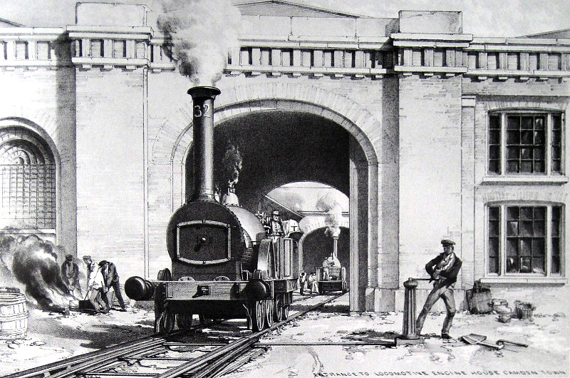
Bury 2-2-0 No. 32 leaving the
original Camden
engine house, by John Cooke Bourne, May 1839.
This locomotive was built by Mather Dixon & Co. of Liverpool.
“The locomotive engines’ station at the
Camden depot is a rectangular building of brick, enclosing an open
quadrilateral space, and is situate on the right side of the railway
going from London, and near to the high chimneys belonging to the
fixed engines. The entrance to this station is by branches from the
main line, which pass under two archways in front of the structure;
in each of these gateways is an engine turn-table, and a
water-column on either side of the way, and above is fixed a large
tank.”
The Railways of Great Britain and
Ireland, Francis Wishaw (1842).
“As
soon as an engine has safely dragged a passenger-train to the top of
the incline at Camden Station, at which point the coupling-chains
which connected it with its load are instantly unhooked, it is
enabled by the switchman to get from the main line upon a pair of
almost parallel side rails, along which, while the tickets are being
collected, it may be seen and heard retrograding and hissing past
its train. After a difficult and intricate passage from one set of
rails to another advancing or ‘shunting’
backwards as occasion may require, it proceeds to the fire-pit, over
which it stops. The fireman here opens the door of his furnace,
which by a very curious process is made to void the red-hot contents
of its stomach into the pit purposely constructed to receive them,
where the fire is instantly extinguished by cold water ready laid on
by the side. Before, however, dropping their fire, the drivers are
directed occasionally to blow their steam to clean; and we may
further add that once a-week the boiler of every engine is washed
out to get rid of sediment or scale, the operation being registered
in a book kept in the office. After dropping his fire, the driver,
carefully taking his firebars with him, conducts his engine into an
immense shed or engine-stable 400 feet in length by 90 in breadth,
generally half full of locomotives, where he examines it all over,
reporting in a book what repairs are wanting, or, if none (which is
not often the case), he reports it
‘correct’. He then takes his lamps
to the lamp-house to be cleaned and trimmed by workmen solely
employed to do so, after which he fetches them away himself. Being
now off duty, he and his satellite firemen go either to their homes
or to a sort of club-room containing a fire to keep them warm, a
series of cupboards to hold their clothes, and wooden benches on
which they may sit, sleep, or ruminate until their services are
again required; and here it is pleasing to see these fine fellows in
various enjoying rest and stillness after the incessant noise;
excitement; and occasional tempests of wind and rain; to which ― we
say nothing of greater dangers ― they been exposed.”
Quarterly Review, Volume
LXXXIV (1848).
Edward Bury’s weak-winded 4-wheeled engines were soon rendered
obsolete by developments in locomotive engineering, and were
eventually replaced with more powerful 6-wheelers. One outcome
from this change was that the
turntables in the original engine house were rendered too short to handle their longer replacements, while
the building was too small to accommodate anything larger. To
complicate matters further, a reduction in freight rates during 1845
led to a sudden increase in the volume of goods passing
through Camden. The outcome
was that in order to enter or leave the engine house, locomotives had to
cross lines that were being used increasingly to marshal freight trains, while down passenger trains,
which no longer needed to stop at Camden to acquire their locomotive
(the stationary winding engine having by now been abandoned), were crossing the yard at speed. These factors combined to
heighten the risk of collision:
“THE ACCIDENT
ON THE LONDON AND BIRMINGHAM
RAILWAY . . . . The mail train which
leaves Birmingham (having previously arrived from Liverpool) at
fifty-five minutes after twelve, at night, is due at the London
terminus at thirty-two minutes after five. About a quarter past five
on Tuesday morning this train arrived at the Chalk-farm end of the
tunnel, and proceeded at full speed onwards towards the platform at
the Camden station. The train, which consisted of from ten to
sixteen carriages, including the trucks and post-office vans,
continued its progress until arriving on the London side of
Chalk-farm bridge, where the down luggage train, which was some few
minutes behind its time, was crossing from the branch curve lines
leading to the luggage storehouses on to the main line. The fog was
so thick that it is described as utterly impossible for any one to
see beyond twenty of thirty feet, and the result was, that before
any measure could be taken to stop the speed of the mail train, it
ran into the luggage train, dashing three of the luggage vans, and
three of the carriages in the mail train, literally to atoms.”
Morning Post,
31st July 1845.
Changes were necessary. Widening the Chalk Farm Bridge allowed extra lines to be built
into the Depot, thereby helping to separate passenger traffic from
other activities. In 1846, the original engine house was replaced by two new buildings at opposite sides of the yard
for handling passenger and ‘luggage’ (goods) locomotives respectively. The goods engine house, known today
as the ‘Roundhouse’, is one of the few buildings from the
Railway’s early years to survive:
“The goods engine-house is circular, and
160 feet in diameter, having twenty-four lines of railway, each
sufficient for an engine and tender, radiating from a central
turnplate 41 feet in diameter. This form of building was found best
adapted to the situation in which it is placed. The turnplate is one
of Handcock’s, made by Messrs.
Lloyds, Foster, and Co.; the struts and beams are of oak. To guard
against damage to this table, from engines running upon it from any
line not corresponding with that on the revolving top, a strong
casting is fixed round the periphery of the top, and projects
upwards to the level of the rails. This casting has no apertures for
the flanches of the wheels, except at the ends of the rails upon the
table itself; thus an engine cannot easily be run upon it, except
when the revolving top is so turned that the two sets of rails shall
correspond.”
Paper by R. B. Dockray published in
the
Proceedings of the Institution of Civil Engineers, Volume 8
(1849). |

The goods engine house at Camden,
known today as the ‘Roundhouse’.
The conical slate roof has a
central smoke louvre (now glazed) and is supported by 24 cast-iron
Doric columns arranged
around the original locomotive
spaces and a framework of curved ribs.
Camden Depot in 1847
Reproduced by
kind permission of Peter Darley,
Camden
Railway Heritage Trust.
|
After about a decade in
use, the Roundhouse also became too small to fulfil its intended role. Over the decades that followed it served various unrelated purposes,
including some 50 years as a bonded store for Gin distillers W. & A. Gilbey
Ltd. In recent years the building has become associated with
the performing arts . . . .
Restored to something of its original condition, the Roundhouse is
now regarded as a notable example of mid-19th century railway
architecture and, as such, was declared a National Heritage Site in
2010.
|
CHAPTER
10
――――♦――――
|
FOOTNOTES. |
|
1. |
Euston Road was then known as ‘The New Road’. In
1852, the central section of The New Road, between Osnaburgh Street
and Kings Cross, was renamed Euston Road, the eastern section became
Pentonville Road and the western section Marylebone Road. |
|
2. |
For surveying, the
statute mile is divided into eight furlongs; each furlong into ten
chains; each chain into four rods (also known as poles or perches);
and each rod into 25 links. This makes the rod equal to 5½ yards or
16½ feet in both Imperial and U.S. usage. |
|
3. |
Stephenson’s plan for
Euston Station had been approved in the previous month. |
|
4. |
Roscoe and Lecount, who state the outturn was £91,528. |
|
5. |
“BATTER: the face of a retaining or other
wall when built in a leaning position, the top part falling back
within the line of base; walls of this description are sometimes
termed, ‘tallus walls’. The batter of a wall is either straight or
curved; the latter are also generally commenced straight from the top, the greatest degree of curvature being given to the bottom of
the wall. The average rate of the batter of the walls upon the
London and Birmingham Railway is 2½ inches to the foot, and 1 inch
to the foot for the wing walls of bridges.”
From
A Glossary of Civil Engineering, S. C. Brees (1844). |
|
6. |
“PUNNING: a
mixture of good tempered clay and sand reduced to a semi-fluid
state, and rendered impervious to water by manual labour, as working
and chopping it about with spades. It is used for the purpose of
retaining the water in any particular situation, or for excluding it
from any works: and it is usually spread in layers of about 12
inches in thickness.”
From
A Glossary of Civil Engineering, S. C. Brees (1844). |
|
7. |
“COUNTERFORT:
a pier or buttress, generally applied at the back of retaining walls
in modern civil engineering, for the support of the same, and
likewise for the purpose of forming a tie to the material at the
back of the wall. Counterforts are also sometimes carried up upon
the face of a wall.”
From
A Glossary of Civil Engineering, S. C. Brees (1844). |
|
8. |
F.
W. Simms, Public Works of Great Britain (1838). |
――――♦―――― |
.htm_cmp_poetic110_bnr.gif)