|
. . . . AND THOSE AROUND TRING
CHAPTER III.
HOW A WINDMILL WORKS
INTRODUCTION
Little change occurred in windmill design from their first use in
Britain until the Industrial Revolution, when a number of
significant advances were made in the design of sails and machinery. But important though they were, these advances were slow to gain
acceptance and too late to make a significant impact, for by then
James Watt’s condensing steam engine was in the ascendant. From
about the mid-19th century, steam-powered milling began rapidly to
supplant wind and water power. This was followed by the introduction
of industrial-scale flour mills in which steel rollers replaced
grindstones to produce, in greater quantity, finer and more
consistent quality products. Mead’s (later Heygates) Flour Mill at
Tring (Chapter VII) is an early example of an industrial-scale flour
mill.
This chapter describes the general operation of a windmill and some
of the advances in design that were made towards the end of the
windmill era. A brief description of the modern roller mill is given
in the Appendix.
WHAT A WINDMILL DOES
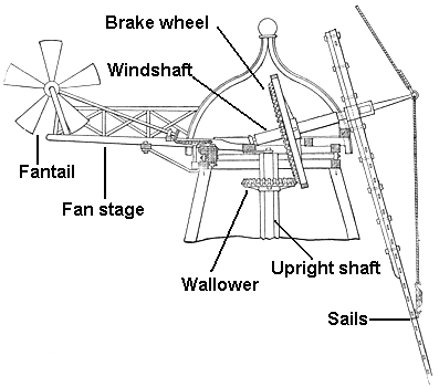
Fig. 3.1: the fantail (where one is
fitted) rotates the cap
automatically to keep the sails facing the wind
The mill was the first engine invented by man. For centuries, mills
driven by water or wind were the only machines that could convert
the power of nature into useful work. In the case of the windmill,
wind striking its sails exerts a force upon them that causes the
shaft to which the sails are attached to rotate. What then follows
depends on what task the windmill is to perform. Windmills have been
used for many purposes, such as pumping water, sawing wood and as
crushing machines in the preparation of oil, paper, spices, chalk
and pottery. Today, wind turbines are used increasingly to generate
electricity. But in Britain, the windmill’s most common use over the
centuries was to grind grain.
In a grain mill, the wind’s energy, harnessed by the windmill’s
sails, is transferred via a system of shafts, cogs and belts to
drive one or more pairs of millstones. Grain, fed between the
rotating millstones is ground into meal.
The remainder of this chapter describes the main steps in the
windmilling process; also the sails and the machinery that is usually
found within a windmill.
THE FLOORS OF A WINDMILL
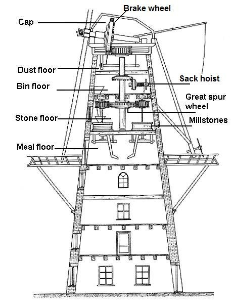
Fig. 3.2: schematic drawing of a
tower mill
Windmills do not follow a common design but they do share common
features, not least of which is that windmilling is a gravity-driven
process. Milling begins at the top of the mill and each succeeding stage
of the process is performed on the next floor down (in following
this process, the need for a mechanically powered hoist to lift sacks of grain
and meal up several floors of a windmill soon becomes clear!)
Windmills were built with different numbers of floors, [3] hence, the
windmilling process is not always exactly as described below. However, in general the following applies . . . .
i. The cap, uppermost part of a windmill (fig. 3.1), houses the windshaft,
bearings, cogs and the top of the upright shaft, which transmits the
windshaft’s rotary motion down through the mill to drive the
machinery.
ii. The dust floor (fig.3.2), positioned under the cap, serves to
keep dirt from above from falling into the storage bins and to keep
dust rising up from below.
iii. The bin floor houses bins in which are stored grain for
cleaning; cleaned grain for milling; and meal to be sifted.
iv. The stone floor houses grain-cleaning machinery, the millstones
used to grind the grain, and machinery to sift the ground meal into
various grades of fineness.
v. The meal floor houses chutes from the stone floor above, down
which flows cleaned grain for milling, meal for sifting, and milled
products, each of which is collected in sacks.
THE WIND MILLING PROCESS
The first step in the milling process is to hoist the grain to be
milled up to the bin floor where it is loaded into a storage bin
ready to be cleaned. When required, the uncleaned grain is
discharged down a chute to the stone floor, where it is mechanically
cleaned, then discharged down a chute for collection on the meal
floor.
Sacks of cleaned grain are hoisted up the mill to the bin floor,
where they are stored in a bin ready for milling. When required, the
cleaned grain is discharged down a chute into a hopper on the stone
floor, from where it is trickled into the millstones, ground and
discharged down chutes for collection on the meal floor.
The sacks are then hoisted up the mill to the bin floor, from where
the meal travels downwards, this time through a flour dresser, which
sorts and distributes it according to its fineness, white flour
being the finest and bran the coarsest. All this machinery is powered
by the thrust of the wind as harnessed by the windmill’s sails.
THE SAILS
|
 |
|
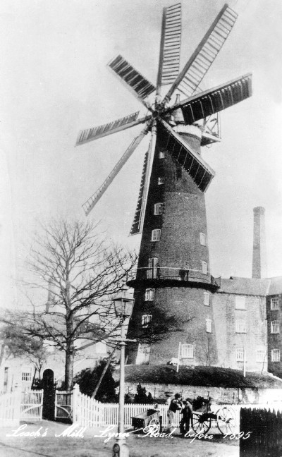
Fig. 3.3: Leach’s
Mill, Wisbech. Ceased milling ca. 1895. |
A
windmill’s sails are usually four in number, but five, six and
eight-sailed windmills (fig 3.3) were also built. More sails
generate more power with a smoother torque, but at greater cost,
weight and maintenance.
A windmill’s sails do not rotate in the vertical plane, but are
slightly inclined to it, for it was discovered that a slight
inclination of about 15° increases the wind’s effect (fig. 3.4). This is due to wind currents near to the ground meeting more
frictional resistance than higher up, to the extent that at a level
of 43 ft above ground-level, wind velocity is some 10 per cent
greater than at 20 ft. To accommodate the tilt of the sails, the windshaft
has also to be inclined at the same angle below the horizontal, with
its rear end held in place by a firmly-embedded bearing to enable it
to rotate while preventing it from sliding backwards (plate 17;
plate 25).
A further discovery was that sails worked more efficiently if,
rather than being set flat across the sail stock, a slight twist is
applied, this being more accentuated nearest the windshaft (about
18°) lessening towards the tip (about 7°); this twist can be seen in
the sails of Quainton mill (plate 26).
A major problem for the miller was to regulate the speed of rotation
of the sails and thus of the millstones. The optimum sail speed for
a grain mill generally lies in the range 11 to 15 revolutions per
minute; speeds much above that run the risk of over-driving the
stones and burning the grain, while even higher speeds — sometimes
referred to as the mill ‘running away’ — could damage the machinery
and, indeed, the mill itself.
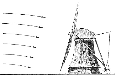
Fig. 3.4: flow of air currents
near the ground.
Small differences in sail speed can be adjusted by changing the
amount of grain fed to the millstones or changing the gap between
them, both of which affect the load placed on the sails. But a large
change in wind speed has to be dealt with by altering the sail area
exposed to the wind, either by increasing or reducing it, a process
called reefing (fig. 3.5).
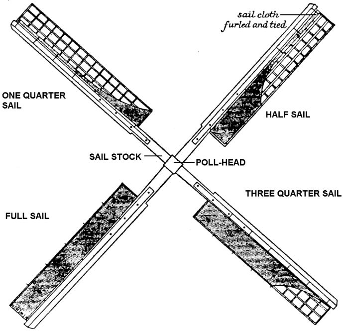
Fig. 3.5: different degrees of
reefing a simple cloth covered sail.
For centuries before the development of more advanced and better
controlled sail systems, sails comprised a lattice framework over
which the sailcloth was spread (plate 10). Such common sails
required two men for reefing, one to climb on the sweeps to carry
out the task and one to control the brake; should the brake fail
during the operation, the man on the sweep was in for a spectacular
ride.
Towards the end of the 18th century, developments in sail design
eased the reefing process. Roller reefing employed banks of cloth
blinds mounted on rollers (comparable to a household roller blind)
that could be adjusted with a manual chain from the ground without
stopping the mill. Other systems replaced the sailcloth with sets of
wooden shutters (comparable to Venetian blinds) mounted along each
sweep. These systems employed some form of tensioning that caused
the shutters to spill the wind automatically if its force exceeded a
set limit. A later invention, the air brake (fig. 3.6), comprised
shutters placed longitudinally at the tip of each sweep that turned
automatically if the wind exceeded a set strength, thereby
disturbing the sail’s profile and slowing it.
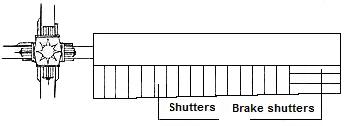
Fig. 3.6: top, a sail fitted
with shutters and air brake.
Bottom, a sail for simple cloth covering.
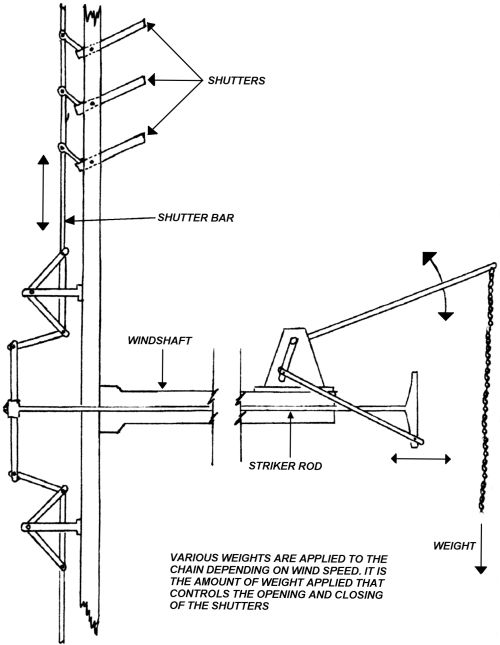
The development of hollow windshafts permitted control rods to be
inserted through their centre (fig. 3.7). This enabled sail settings
to be adjusted from within the mill automatically under the action
of counter-weights.
|
Fig. 3.7: towards
the end of the windmill era, shuttered sails were
introduced that enabled a degree of automatic reefing by
applying tension weights to balance the wind pressure
falling on the shutters. The two forces were
balanced through the striker rod (which passes through
the centre of the windshaft), the shutters bars and
moveable linkages/levers. |
While these developments were not without their complexities when
compared to common sails, they reduced manual effort while improving
the windmill’s efficiency as a motive force.
THE MACHINERY
Different hardwoods were used in the construction of milling
machinery. Cogs were often of applewood, hornbeam or beech, wheels
and shafts of oak, whilst the dowels used to join together wooden
parts were of holly. However, from the middle of the 18th century
cast-iron parts were used increasingly, although iron-to-iron
gearing was avoided, for it was found that iron-to-wood gearing ran
more quietly and was easier and cheaper to maintain and, most
important, it avoided the risks of sparks causing a dust explosion. [4] Problems
associated with manufacturing and handling large iron castings were
avoided by the use of small sections bolted together, an example
being the dozen or so sections that make up the 18ft diameter iron
rack in the cap of Wendover mill (plate 24).
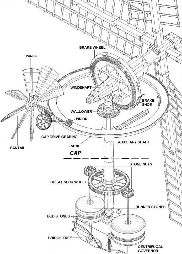
Fig. 3.8:
general arrangement of a windmill fitted with a cap and fantail, and
two sets of stones.
In order to rotate the millstones, the (near) horizontal rotation of
the windshaft must first be converted into a vertical rotation. This
is achieved using a form of bevel gearing. The inner end of the
windshaft is fitted with a large toothed wheel, the brake wheel, the
teeth of which mesh with a cog, the wallower, which is set at an
upright angle to it. The brake wheel, when rotated by the windmill’s
sails in the horizontal, causes the wallower to rotate in the
vertical (fig. 3.8).
The wallower is mounted on the upright (or main) shaft, which
transmits its rotary motion downwards through the mill. Mounted on
the base of the upright shaft is another large toothed wheel, the
great spur wheel. This in turn meshes with the cogs — called stone
nuts — that drive the millstones. In this way the wind’s energy is
captured and then put to work to grind grain and drive other
machinery for cleaning, sifting and hoisting grain.
As its name implies, the brake wheel’s other function is to stop the
mill. In fig. 3.8, the brake is the circular shoes that surround the
brake wheel. To stop the mill, a lever is pulled to tighten the
brake-shoes causing them to grip the periphery of the brake wheel
and thus slow the rotating windshaft or clamp it in place.
THE MILLSTONES
Windmills are generally equipped with several sets of millstones (plate
14). Each set comprises a rotating runner stone and a stationary bed
stone which, depending on their diameter, weigh in the region of two
tons. Different types of stone are used to grind different types of
grain. Stones of grey millstone grit from Derbyshire are used to
grind coarse meal for stock feeding. The millstones employed to
grind wheat for flour are made of French Burr, a hard silicate found
in the Seine valley. Burr stones are constructed in segments,
cemented together and bound with heavy iron bands.
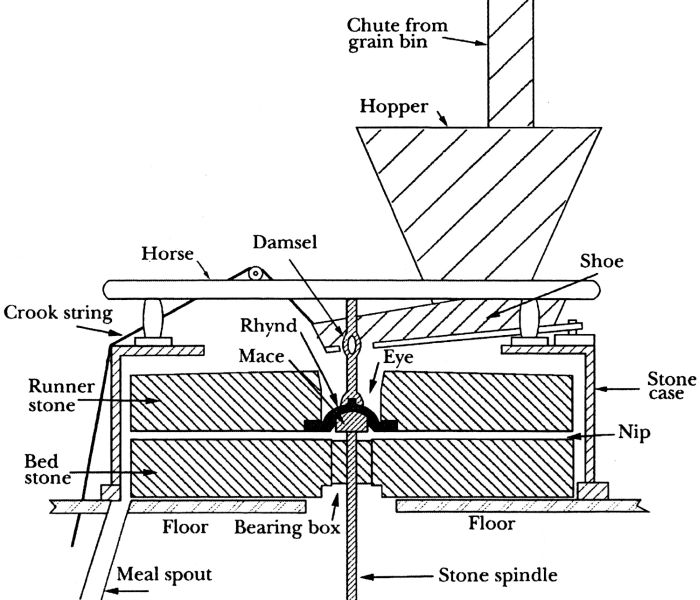
Fig. 3.9: millstones and their
associated equipment.
In operation, the millstones (fig. 3.9) are fed from a hopper, which
trickles grain along a wooden trough — the shoe — into the eye (a
hole through the centre of the runner stone) where it is ground
between runner and bed stones. The shoe is kept in a continual state
of agitation by a rotating crank. Called the damsel, due to its
chattering sound when in operation, it serves to keep the grain
flowing steadily down the shoe into the eye.
Each stone has a pattern of grooves cut into its surface (fig. 3.10). The
grooves act like scissors, cutting the grain as well as moving it
outwards from the centre to the periphery of the millstones. As the
meal emerges from between the stones, it is swept inside the
circular wooden container that encases them — the tun or stone case
— into the top of a chute, or meal-spout, which funnels it down to
the meal floor below where it is bagged.
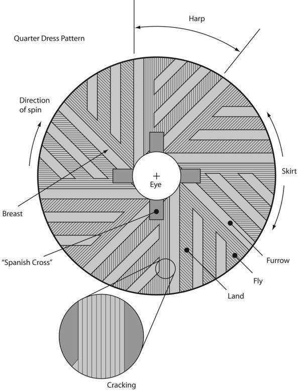
|
Fig. 3.10:
plan view of a millstone. This is a runner stone;
a bedstone would not have the "Spanish Cross" into which
the supporting millrynd fits. |
In regular use, the grooves in a millstone wear down and need to be
dressed periodically; that is, re-cut to keep their cutting surfaces
sharp. This is a tedious and exacting task, sometimes
performed by the miller but often by an itinerant stone dresser
(fig. 3.11). The work was
executed using various tools including a mill bill, a
tempered steel blade clamped in a wooden handle, rather like a small
pickaxe, and used as a chipping tool. Today, power tools are often
used.
|
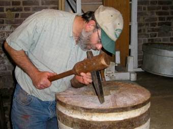 |
|
Fig. 3.11: a stone
dresser using a mill bill. |
Adjusting the gap between the stones — a process called tentering —
is carried out using a system of screws or levers that move the
runner stone up or down. This gap, or nip as millers call it, helps
to determine the fineness of the meal; the smaller the nip, the
finer the meal. Only slight adjustments are required, for the
stones, when grinding, are only about the thickness of a postcard
apart.
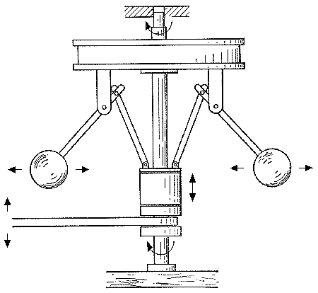
Fig. 3.12: the centrifugal
governor.
Tentering can be performed manually, but the centrifugal governor
(fig. 3.12 & plate 2) can perform the task more efficiently. This ingenious
device is driven from the rotating upright shaft. As the speed of
rotation of the sails — and thus of the shaft and the millstones —
increases, a pair of heavy metal balls linked to the governor’s
spindle begin to fly outwards under the increasing centrifugal
force. This causes their collar to rise up the spindle, and in so
doing to move the levers that adjust the gap between the millstones. An increased gap results in more grain being fed into the eye of the
millstones, which increases the load on the sails, slowing their
speed of rotation and that of the millstones.
The optimum speed of rotation of a runner stone depends on its
diameter and on the quality of the output required. A rule of thumb
followed by millers was to divide the diameter of the stone (in
inches) into 5,000 for flour and 6,000 for coarser meal. Thus the
optimum speed for a 48 inch runner stone, set to produce meal, would
be 125 rpm — assuming, of course, there was sufficient wind to drive it at that
speed.
THE FANTAIL
Even a small change in wind direction can result in a significant
reduction in the torque the sails generate if they are not
repositioned. In older windmills, ‘winding the mill’ involved hard
manual effort. In the case of a post mill, the entire superstructure
needed to be turned by pushing on a large beam (the tail post) that
protruded from the rear of the mill. In later smock and tower mills,
only the top floor (fig. 3.1) needs to revolve, but this still
required manual effort. The fantail automates the process by using
the wind itself to wind the sails. Later windmills usually adopted
this feature, which could also be built onto the tail posts of old
post mills (plate 31).
A fantail comprises gearing driven by a small set of sails (vanes),
which are aligned at right angles to the main sails and positioned
at the rear of the mill. Its purpose is to rotate the cap
automatically when a change of wind direction occurs, which it
achieves via a system of gears that mesh with a toothed rack around
the inside of the cap (fig. 3.8). When the sails are properly
winded, the vanes of the fantail are at right angles to the wind, so
they derive no thrust from it and
do not rotate. But should the wind change direction, its force then
falls on one side or the other of the fantail, causing its
vanes to rotate and drive the gearing that rotates the
cap and winds the sails, a clever feat of automation.
However, while very useful in normal working conditions, the fantail
provided no guarantee against a mill being tail-winded by a sudden
change in wind direction, as sometimes accompanies a thunderstorm;
thus fantails might be supplemented by a hand crank, an example
being in the cap of Wendover mill (fig.
10.3). And unless the fantail drive
could be disconnected, a further problem for the miller was how to
turn the windmill’s sails off the wind in a sudden squall in order
to stop them. Things were rarely straight-forward in windmilling.
ANCILLARY EQUIPMENT
|
 |
|
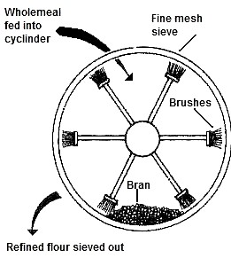
Fig. 3.13:
principle of the flour dresser. The cylinder is tilted
at an angle. The wholemeal is fed into the upper
end and passes through the machine under gravity, the
bran being ejected at the lower end. |
Because windmills use gravity feed to clean and grind grain, filter
the meal produced and bag the end product, a sack hoist is an
essential piece of equipment if the drudgery of lifting sacks
manually up the mill, on numerous occasions, is to be avoided. The
sack hoist takes the form a simple rotating chain, driven by an
auxiliary shaft which is in turn geared to the upright shaft (plate
3). As it rotates, the sack hoist is used to lift the sacks of grain
or meal up through a succession of trapdoors to the bin floor of the
mill.
The auxiliary shaft also powers other windmill machinery. That used
prior to the grain being milled might include a smutter, which removes the
black spots of smut caused by a fungus disease that can grow on
grain if its gets damp; a separator, used to separate grain from
other foreign matter, such as stones, weeds, and sticks; a scourer,
used to separate usable grain from debris such as dirt, dust, and
chaff.
Following milling, a flour dresser (fig. 3.13) is used to sift the
meal into its various grades of fineness. The dresser consists of a
cylindrical drum, covered in wire mesh of increasing grades of
fineness, and set at an angle. Inside the drum revolves a set of
brushes. Meal, fed into the upper end of the cylinder is rubbed
against the mesh screens by the brushes as it falls through the
cylinder under gravity. The finest meal, white flour, can pass
through the finest mesh screen; next comes semolina flour, which
passes through the next grade of mesh, leaving the coarsest product,
bran. Each grade is ejected into canvas chutes which feed sacks on
the meal floor below.
The mill might also drive an oat crusher, used to crush oats for
animal feed.
――――♦――――
APPENDIX
THE ROLLER MILL
Although the subject of this book is windmills, some mention should
be made of the technology that in the latter part of the 19th
century was to sweep away both wind and water mills so rapidly.
The steam engine was the first major advance. The first
steam-powered mill, Albion Mill, was established in 1786 by Matthew Boulton and James Watt. It employed a Watt steam engine of 150 hp to
drive 20 pairs of millstones, and was capable of grinding 10 bushels
of wheat per hour, all day and regardless of wind strength. Albion
Mill was the industrial wonder of the age, but in 1791 it burned
down. The cause was never discovered, but it was widely believed to
be an act of arson by local millers and millworkers who believed
their livelihood was threatened by the new technology.
Rotating millstones, sometimes steam-driven, continued to be used
for grain milling until the late 19th century, when roller mills — a
Swiss invention — appeared, the first being built in Hungary in
1874. Edward Mead (Chapter VII.) is believed to have installed the U.K.’s
first roller mill at Chelsea in 1881. The combination of steam power
and the roller milling process led directly to the flour mills of
today.
|
 |
|
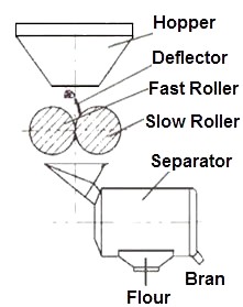
Fig. 3.14:
the principle of the roller mill. In practice, the
meal passes through several stages of roller milling to
produce fine white flour. |
Roller milling (fig. 3.14) crushes the grain, not between revolving
millstones, but between a series of fluted steel rollers of about 12
inches in diameter. The rollers are set with a specified gap between
them and spin towards each other at high, but at different, speeds;
the surface of each roller is also grooved with a different pattern.
In a modern flour mill, before milling commences, the grain is
cleaned of any extraneous matter using a variety of techniques
including sifters and magnets (to remove metallic particles). It is
then conditioned to ensure uniform moisture content and blended with
other wheats to provide a mix capable of producing flour of the
required character. Then, using a reduction process, the grain is
crushed by a succession of rollers, the fine flour particles being
sifted out at each pass of the rollers while the residue (bran) is
sent on to the next set of rollers in a repetitive manner. Thus,
roller milling is a series of crushing and sifting operations,
ideally suited for making clean white flour.
Roller mills offer several other advantages over traditional milling
methods. They eliminate the cost of dressing millstones and enable
the production of a larger amount of better-grade flour from a given
amount of wheat, quicker and to a consistent standard. Rollers are
also superior for milling the harder wheats used for bread by
reducing the wheat kernel slowly into flour fragments to separate
out the bran.
Roller milling made possible the construction of larger, more
efficient grain mills, hastening the abandonment of the small
country wind and water mills, and of stone grinding. Indeed, so
successful were the roller mills that within 30 years of their
introduction into Britain in 1881, more than three-quarters of the
wind and water mills that had served for centuries so faithfully, if
erratically, had been demolished or abandoned. This is what Edward
Bradfield, an old miller who was writing in 1920, had to say about
this milling revolution . . . .
“Then came the changes. ‘High grinding,’ ‘gradual reduction’ and the
‘roller system’, one after the other, came to revolutionize the
trade. The flour was greatly improved by the new methods and the
trade of the stone millers was decimated. The new methods allowed
the brittle stony wheats then coming into fame to be made into
excellent flour which the stone millers could not equal. Yet many of
them, who clung to the traditional system which had brought them
fame, wealth and honour, made heroic efforts to stay the onslaught,
but failed.”
However, the roller mill revolution brought with it a drawback. The
friction of the rollers caused the meal to become hot, which led to
some nutrients in the flour being damaged. This was not realized at
a time when essential dietary needs were little understood.
Today, the
‘Bread and Flour Regulations’ govern the use of additives
as well as requiring the addition of certain nutrients to ensure
that a wholesome product emerges from the flour mill. This from the
Federation of Bakers . . . . .
“The Bread and Flour Regulations require that flour should contain
not less than 0.24mg. thiamin (vitamin B1), 1.60mg. nicotinic acid
and 1.65mg. of iron per 100g. of flour. These amounts are found
naturally in wholemeal flour. White and brown flours must be
fortified to restore their nutritional value to the required level.
In addition calcium carbonate, at a level of not less than 235mg.
and not more than 390mg. per 100g. of flour, is added to all flours
except wholemeal and certain self-raising varieties. This ensures
the high nutritional value of all bread, whether it is white, brown
or wholemeal.” |